Continue to Site

Welcome to EDAboard.com

Welcome to our site! EDAboard.com is an international Electronics Discussion Forum focused on EDA software, circuits, schematics, books, theory, papers, asic, pld, 8051, DSP, Network, RF, Analog Design, PCB, Service Manuals... and a whole lot more! To participate you need to register. Registration is free. Click here to register now.

Band Pass FIlter Problem

Status
Not open for further replies.

code2zero

Newbie level 3
Joined
May 3, 2012
Messages
4
Helped
0
Reputation
0
Reaction score
0
Trophy points
1,281
Activity points
1,310
I am designing a Band Pass filter.

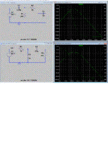
I tried to swap the order in which the filters( LP and HP) are used. and found out that I get two different result. If I calculate the transfer function of the band pass filter I shouldn’t see any difference. But in my case LP-HP band pass filter has more loss than HP-LP filter. Can anyone explain this why this is happening. Please find the attached gif file for circuit and simulation.

~kk
Band_pass_problem.gif
 

In both cases, the second filter loads the output of the first filter, changing it's characteristics. To minimize that effect, the impedances of the second filter should be much higher than the first filter. Your high-low filter gets that right (1K>>200 Ohms). To improve the low-high filter, try setting R2 = 5K and C2 = 0.1uF.
 
Thanks, I understand now about the loading part.

I want someone to point where i am doing something wrong during the derivation of Transfer Function. Because for me the TF looks same for both of them.

---------- Post added at 01:46 ---------- Previous post was at 01:13 ----------

Thanks, I understand now about the loading part.

I want someone to point where i am doing something wrong during the derivation of Transfer Function. Because for me the TF looks same for both of them.

For Low Pass High Pass case
1st stage:
TFlp = 1 / jwR1C1
2nd stage:
TFhp = jwR2C2 / (1+ jwR2C2)

For Low Pass High Pass case
TF(band Pss) = 1st tsage * 2nd Stage = Vhp/Vin = (1/jwR1C1)*(jwR2C2 / (1+ jwR2C2)) --- 1

For High Pass Low Pass case
TF(band Pss) = 1st tsage * 2nd Stage = Vlp/Vin = (jwR2C2 / (1+ jwR2C2)) * (1/jwR1C1) --- 2

Both Eqn 1 and 2 are same:!::shock:
 

:smile:
...and I have no idea what the correct answer is. My math isn't that good.
:oops:
 

Thanks, I understand now about the loading part. ..............
Both Eqn 1 and 2 are same:!::shock:

However, it seems you didn`t understand the "loading part" completely.
Of course, also during calaculation of the TF you have to consider the loading effect.
In detail: You are not allowed to simply calculate both RC terms separately - and then multiply both.
This is allowed only if there is a decoupling buffer between both parts.
Without such a buffer the derivation of the TF is somewhat more involved.

---------- Post added at 09:55 ---------- Previous post was at 09:54 ----------


Hint: Principle of a loaded voltage divider (Kirchhoff laws).
 
  • Like
Reactions: FvM

    FvM

    Points: 2
    Helpful Answer Positive Rating
The problem is simple. You can't use the known equations for first order LP and HP for the combined circuit. The load impedance of the second one changes the transfer characteristic of the first. But it's just elementary AC network calculation.

For the general solution, it's comfortable to refer to a symbolic calculation tool, e.g. Sapwin or xfunc. They have been discussed in various same topic threads.

For the first circuit from post #1 (HP/LP) you e.g. get

H(s) = R1C1s/(1 + (R1C1+R2C2+R1C2)s + R1R2C1C2s^2)

The second circuit (LP/HP) only differs by the denominator

H(s) = R2C2s/(1 + (R1C1+R2C2+R1C2)s + R1R2C1C2s^2)

If you are switching from one to the other topogy, also exchanging the R and C values, the term R1C2 makes the difference.

Thanks , derived and simulated :smile:
 

Status
Not open for further replies.

Similar threads

Part and Inventory Search

Welcome to EDABoard.com

Sponsor

Back
Top