Continue to Site

Welcome to EDAboard.com

Welcome to our site! EDAboard.com is an international Electronics Discussion Forum focused on EDA software, circuits, schematics, books, theory, papers, asic, pld, 8051, DSP, Network, RF, Analog Design, PCB, Service Manuals... and a whole lot more! To participate you need to register. Registration is free. Click here to register now.

Backup battery switching and charging with LTC4020

Status
Not open for further replies.

ferbo

Junior Member level 2
Joined
Feb 1, 2021
Messages
22
Helped
0
Reputation
0
Reaction score
1
Trophy points
3
Activity points
227
Hello everyone.
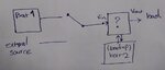
I need to create a circuit that manages seamless switching of the power path from the input voltage to the backup battery in case the input cannot supply current and charge the battery and supply the load when the input voltage is connected.

I have been searching for a chip that would control this function and landed on these from analog devices : LTC4020, 4000,4013

my input will have a range of 35-50 v and the output and backup battery(12s of li-polymer) have a similar range. my load needs 10 A of continuous current.
I need to know if the function I need is possible with these chips and which one is better suited? thank you!
 

Hi,

It's not clear to me where exactly you see a problem..
Please provide more informations, like a sketch, technical details like timing.. and so on..

Klaus
 

There's nothing wrong with wanting to combine a charging circuit in your power supply. However consider that it may be simpler to have the battery provide power continually, and let the charger send whatever amount of juice replenishes the battery. Regulate the supply voltage so it never goes above a level which is safe for the battery. (Prospectively your voltage regulator can be a buck converter, 10 A output)

Notice the result is that the supply is effectively the primary source of electrons, and those electrons pass right by the battery. The battery sits idle most of the time accepting a few mA of trickle current. When it's needed you have seamless changeover (of 10 Amperes) because it's already in the circuit.

Steering diodes may be added, for a measure of protection.

After a blackout the battery needs to be charged. Design the regulator to provide an extra Ampere (while maintaining safe voltage limit), or whatever charge rate suits your needs.

The above setup requires care in design and adjustment. However it takes more effort to create a combination power supply and charging module, which must decide what to do: whether to power a circuit, or charge a battery, or stop charging, or whatever.
 

    ferbo

    Points: 2
    Helpful Answer Positive Rating
Hi,

It's not clear to me where exactly you see a problem..
Please provide more informations, like a sketch, technical details like timing.. and so on..

Klaus
Hi,
Thank you Klaus for you reply. The problem is that I don't know which one would be better for my application and can't understand their main differences. My input will be another battery pack with similar characteristics. this battery pack is the main power and will be exchanged by a voltage source of a similar voltage when it needs to be charged. I need the load supplied continuously while this change is happening or when the main battery pack is discharged.
--- Updated ---

There's nothing wrong with wanting to combine a charging circuit in your power supply. However consider that it may be simpler to have the battery provide power continually, and let the charger send whatever amount of juice replenishes the battery. Regulate the supply voltage so it never goes above a level which is safe for the battery. (Prospectively your voltage regulator can be a buck converter, 10 A output)

Thank you BradtheRad for your help. My power supply is most of the time another battery(let's call it BAT1) and I only need a continuous load supply while BAT1 is discharged or misplaced for a short while.
 

Attachments

  • block(1).jpg
    block(1).jpg
    47.6 KB · Views: 119
Last edited:

Hi,

I have read the datasheets very quickly. LTC4020 and LTC4000 seem to highlight smooth switchover between power sources, LTC4013 doesn't. As far as I have understood what I've read, the first two seem more appropriate for LiPo, the third is more for lead-acid and solar applications but can do Li-ion as well (is that the one that needs a charge-balancing add-on, maybe?). In my non-expert opinion, and bearing in mind my non-detailed reading of every page of three different datasheets, I'd go for the LTC4020 or the LTC4000 or at least investigate them further and maybe see if there are related application notes. Which of the two is better suited? - I have no idea, read quickly, they seem much of a muchness. 10A continuous current? - maybe the 'detailed description' sections shed light on that question.

Sorry I can't be of more help.
 
  • Like
Reactions: ferbo

    ferbo

    Points: 2
    Helpful Answer Positive Rating
Recreational vehicles often have two batteries, which supply separate systems but can be interconnected in some conditions. (Example, it's efficient to have one alternator charge both batteries.)

It might pay to research such setups in case it gives you ideas for your own.
 
  • Like
Reactions: ferbo

    ferbo

    Points: 2
    Helpful Answer Positive Rating
Status
Not open for further replies.

Similar threads

Part and Inventory Search

Welcome to EDABoard.com

Sponsor

Back
Top