Vermes
Advanced Member level 4

Why was this board designed:
- the typical board had bad connections and FT232R
- the LCD always with RW connected to GND
- small processors (ATtiny2313)
- no H bridges
- and more...
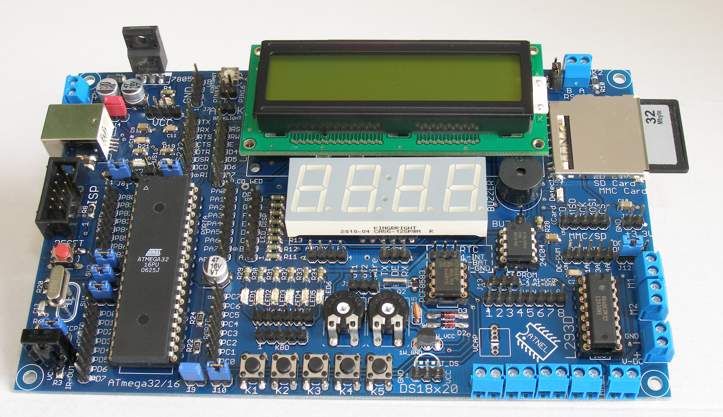
This device:
- USB RS232 on FT232RL
- USB input for boot loader and power from it
- RS485 on SN75176 with possibility to connect to FT232RL
- infrared receiver (with a quick jumper to connect on input ICP input of the processor)
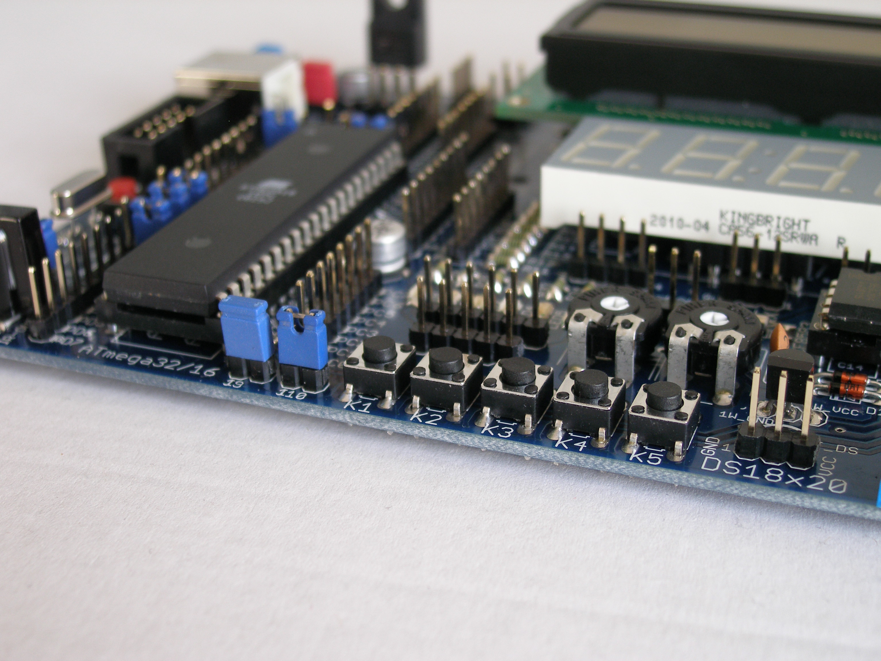
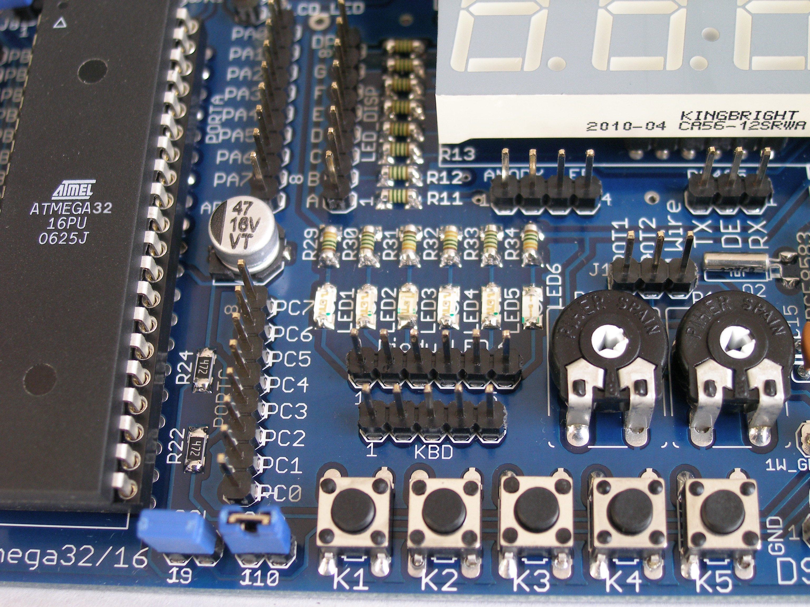
- 7-segment red LED display (4 digits and dots)
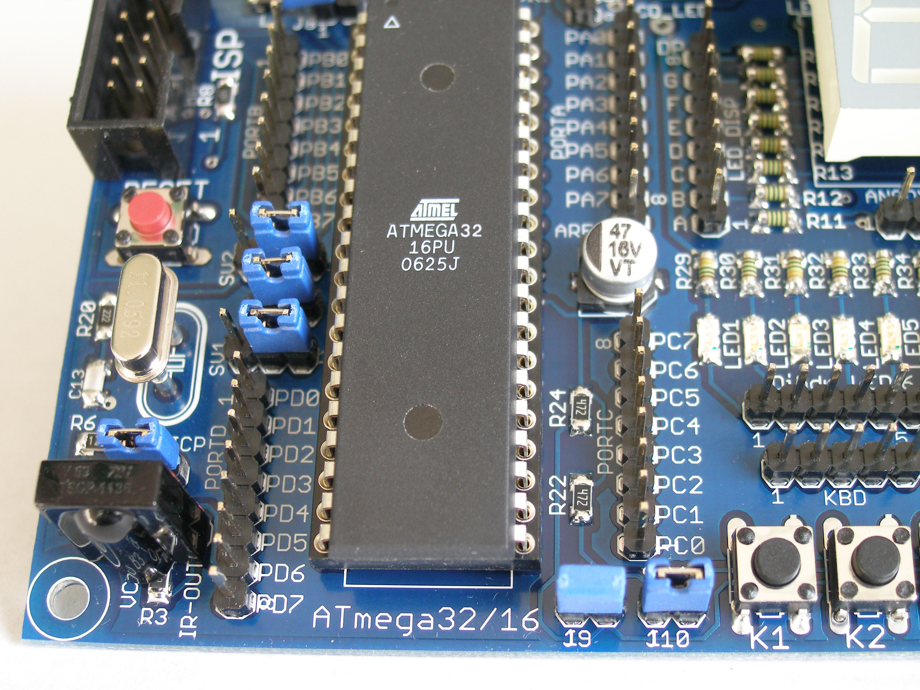
- 5 micro switch buttons
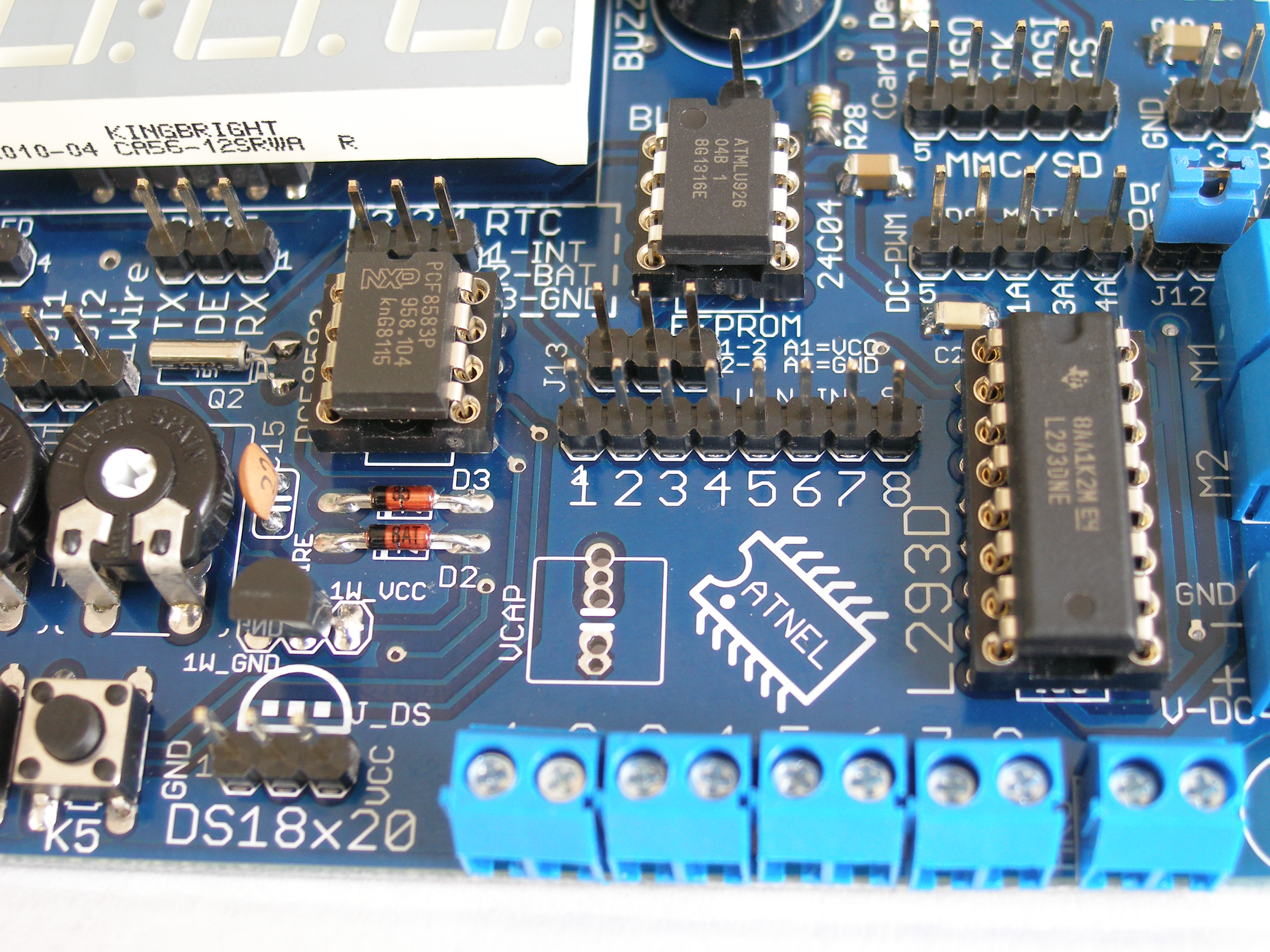
- ULN2803
- possibility of 8 device steering (for for example relays)
- possibility of steering a step-motor
- slot on SD/MMC card
- 2 H bridges in L293D
- steering a PWM or
- 4 DC drives (for for example fans)
- 2 DC drives – left, right rotating
- 1 bipolar step drive
- external EEPROM memory on I2C bus – for example 24Cxx
- RTC – Philips PCF8583 on I2C bus (used for FAT handling on SD cards)
- 1 wire bus with one DS18D20 thermometer, with possibility to connect next ones
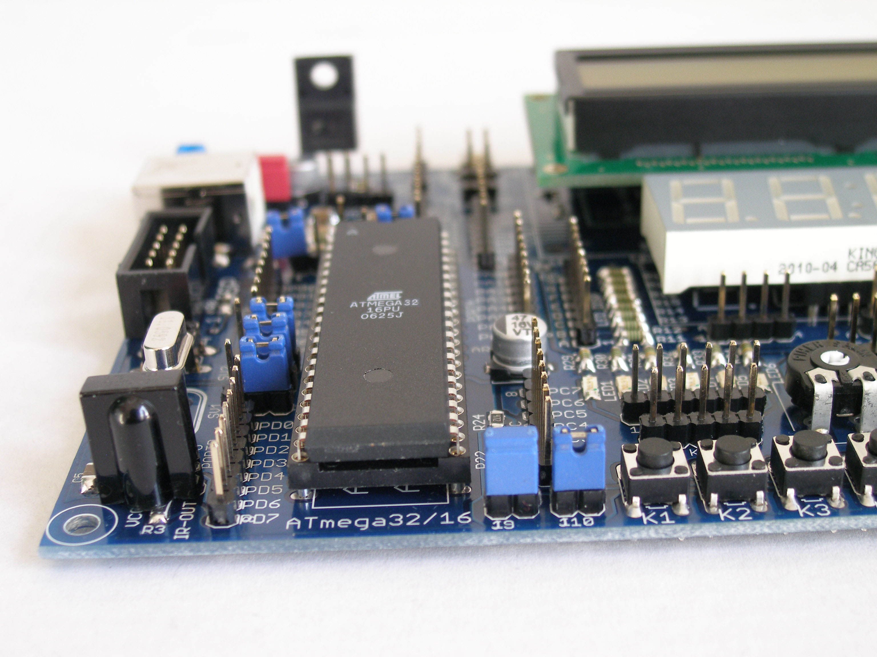
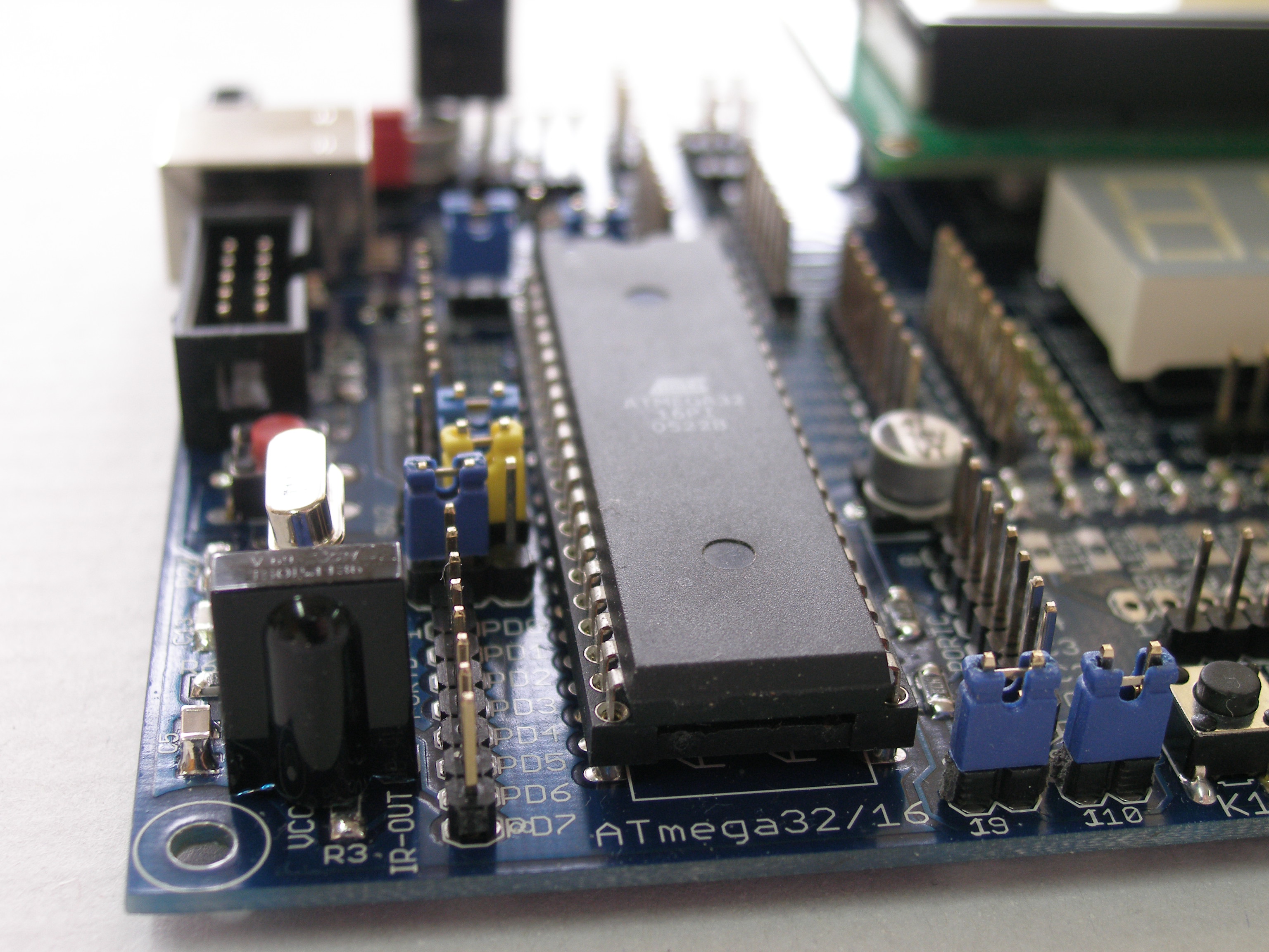
- possibility of using Atmeta32 or Atmega16
- LCD display (with RW GND connection by a jumper)
- adjusting to LCD back light
- Buzzer
- tension stabilizer +3.3V – with possibility of powering external devices
- high capacity capacitor (1F) to sustain the PCF6563 clock
- ISP socket in KANDA standard to the programmer
- RESET button on the board
- two potentiometers (for example ADC convertor)
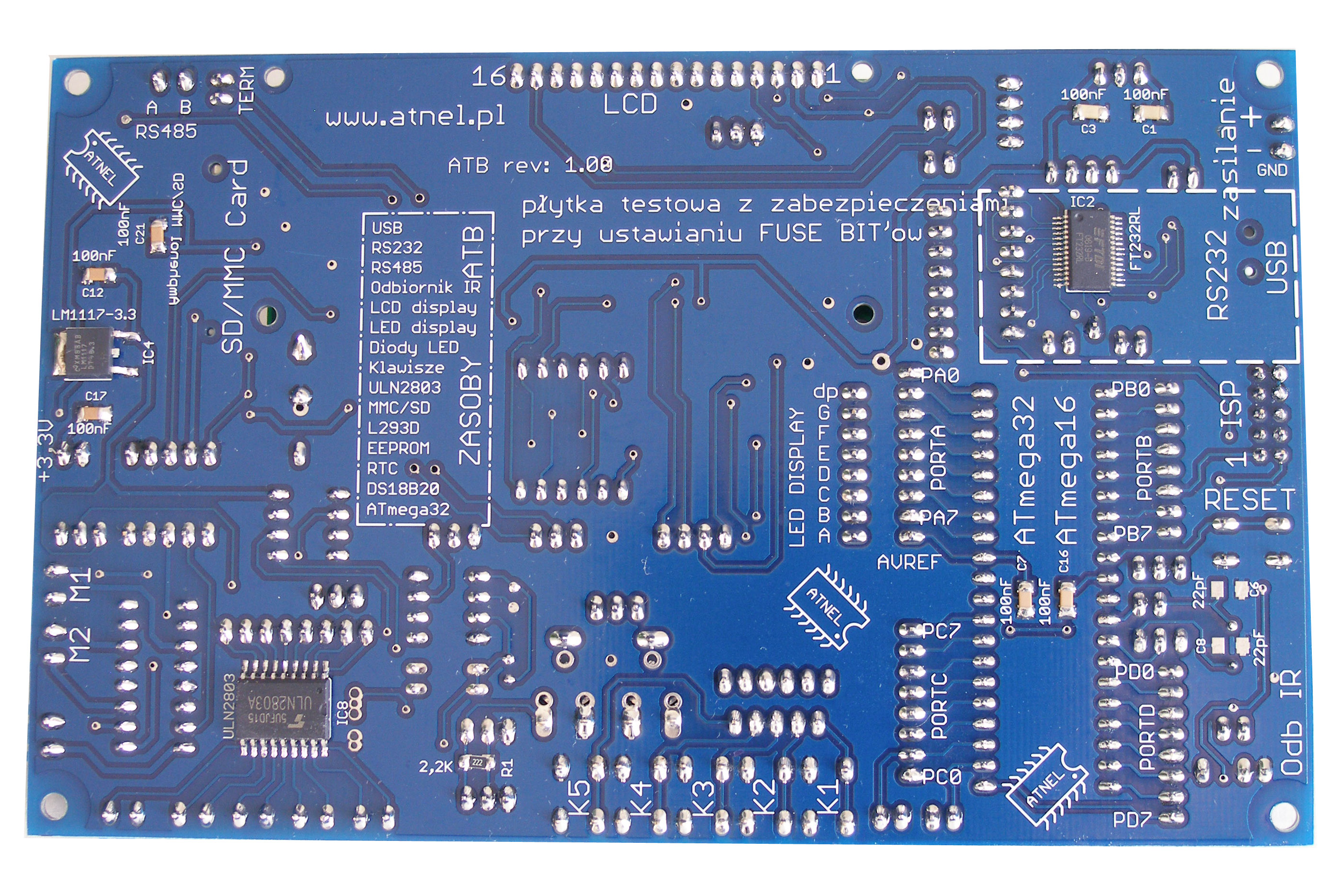
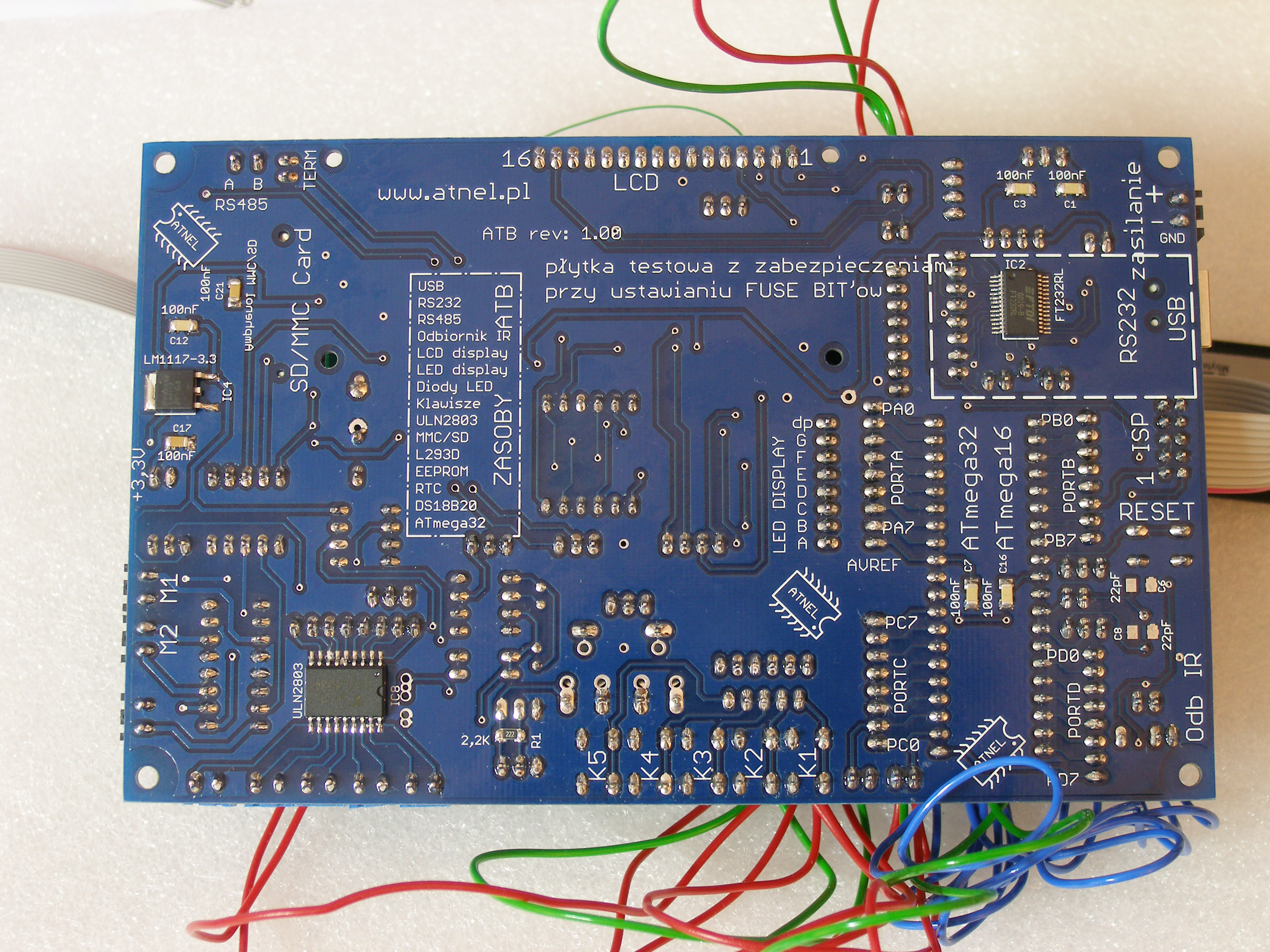
Some of the chips were soldered on the bottom: FT232RL, ULN2803 and LM1117-3.3
Size of the board: 16x10 cm
It can be programmed in: Bascom, C or assembler
The board was designed to prevent the chip from blocking by badly configured FuseBits.
Mounted devices (on the board): RC oscillator, TTL generator.
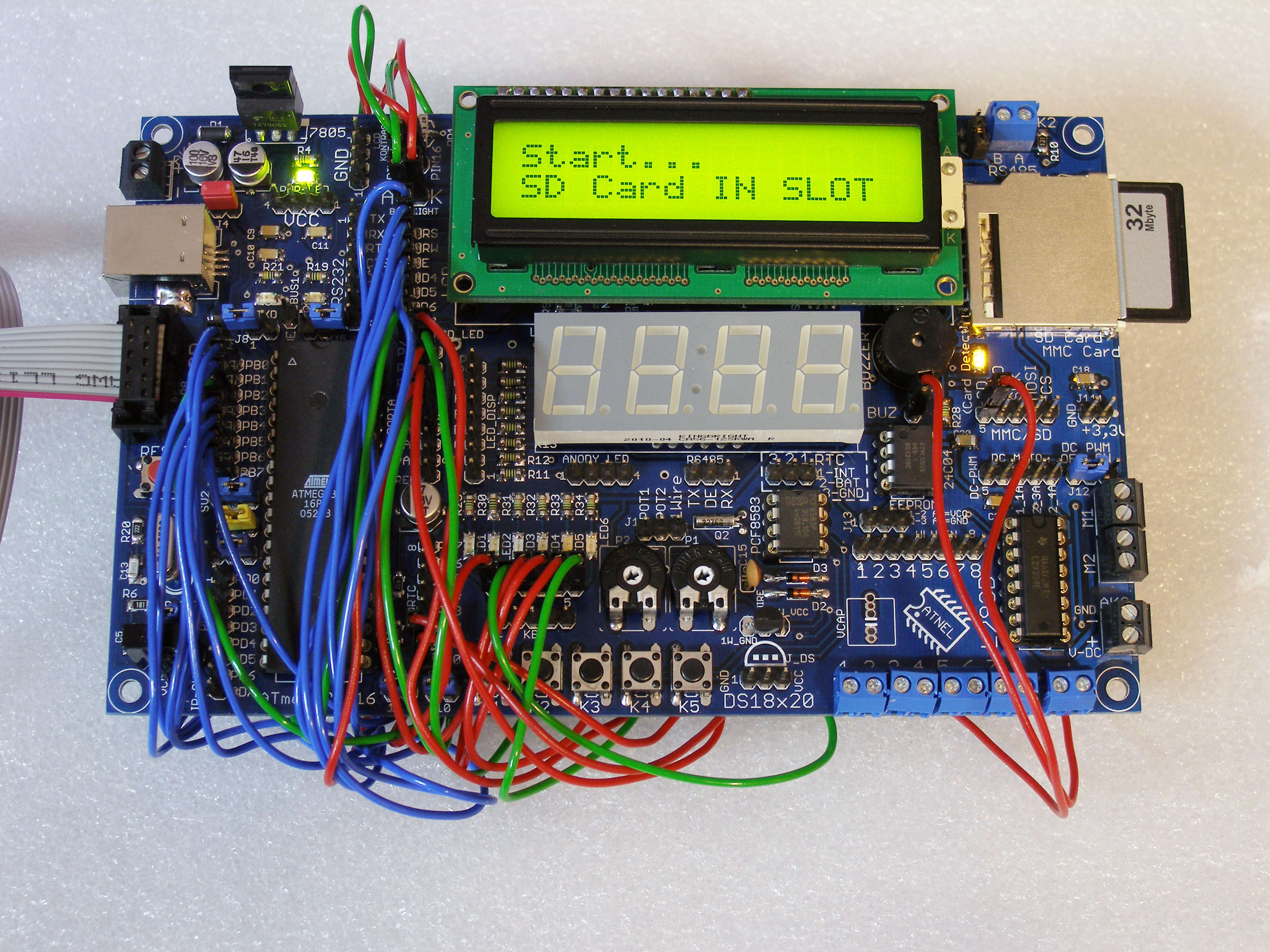
It works very well with: mkBootLoader and mkAvrCalculator
mkBootLoader
mkAvrCalculator
The whole board can be programmed by: USBASP
USBASP
Using jumpers, the power supply can be changed from its own 7805 or to USB.
Using the infrared, the board can be used for building remote controls, for example:
Pilot IR uniwersalny "inaczej" Olympus,Sony,RC5...
plus Index of /remotes
By jumpers, the frequency can be easily changed: to a external quartz, a RC oscillator or to a TTL generator.
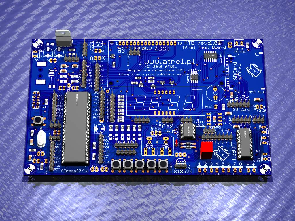
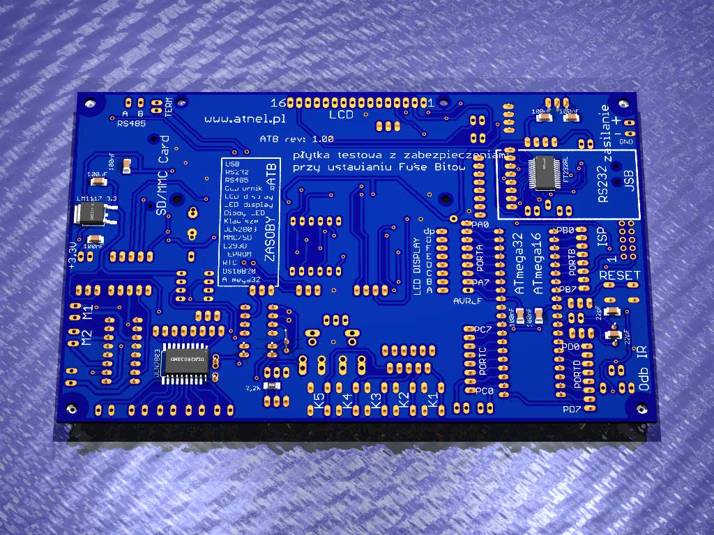
The designed board in 3D in Eagle:
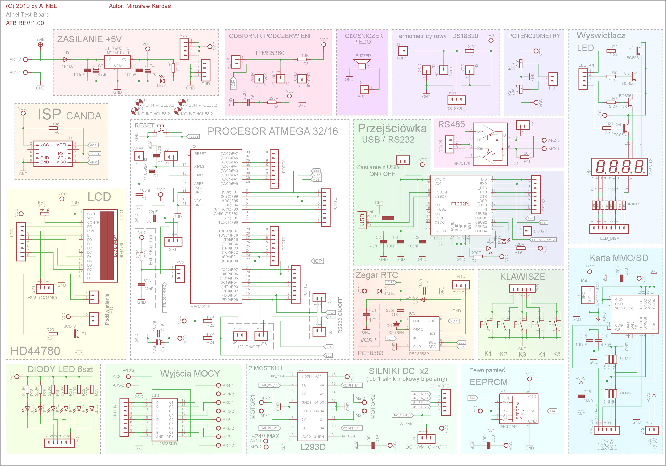
Schema:
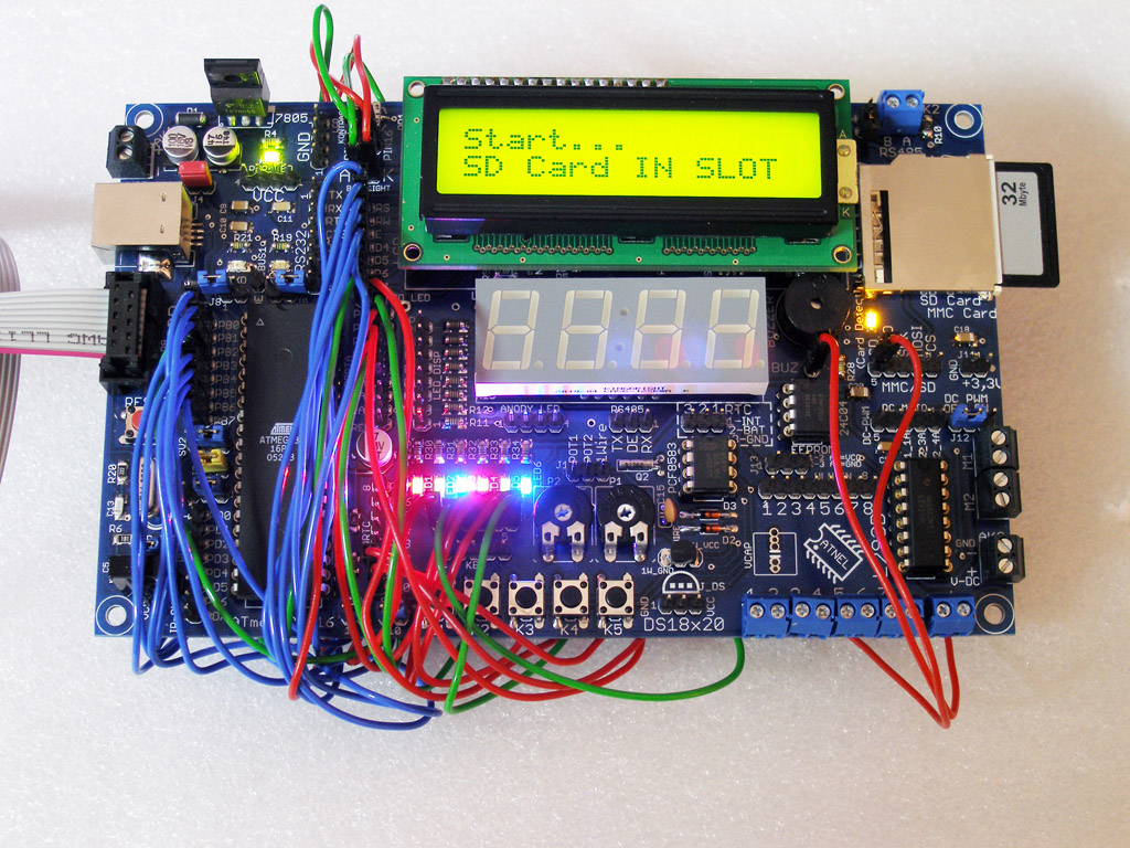
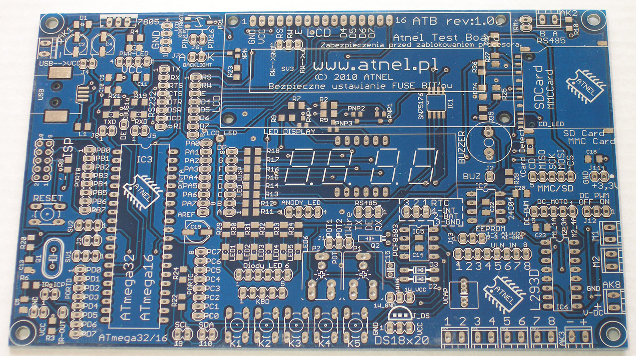
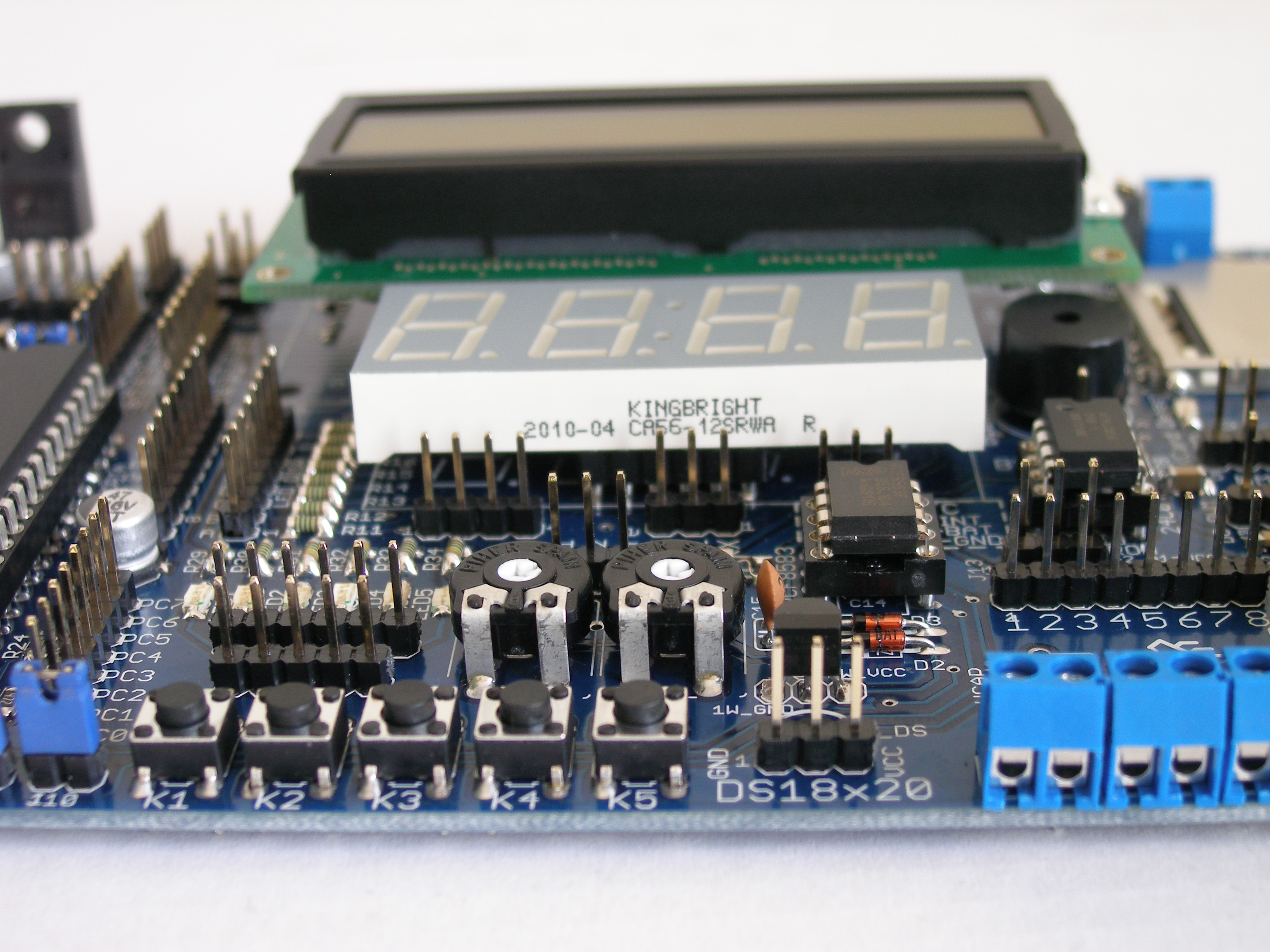
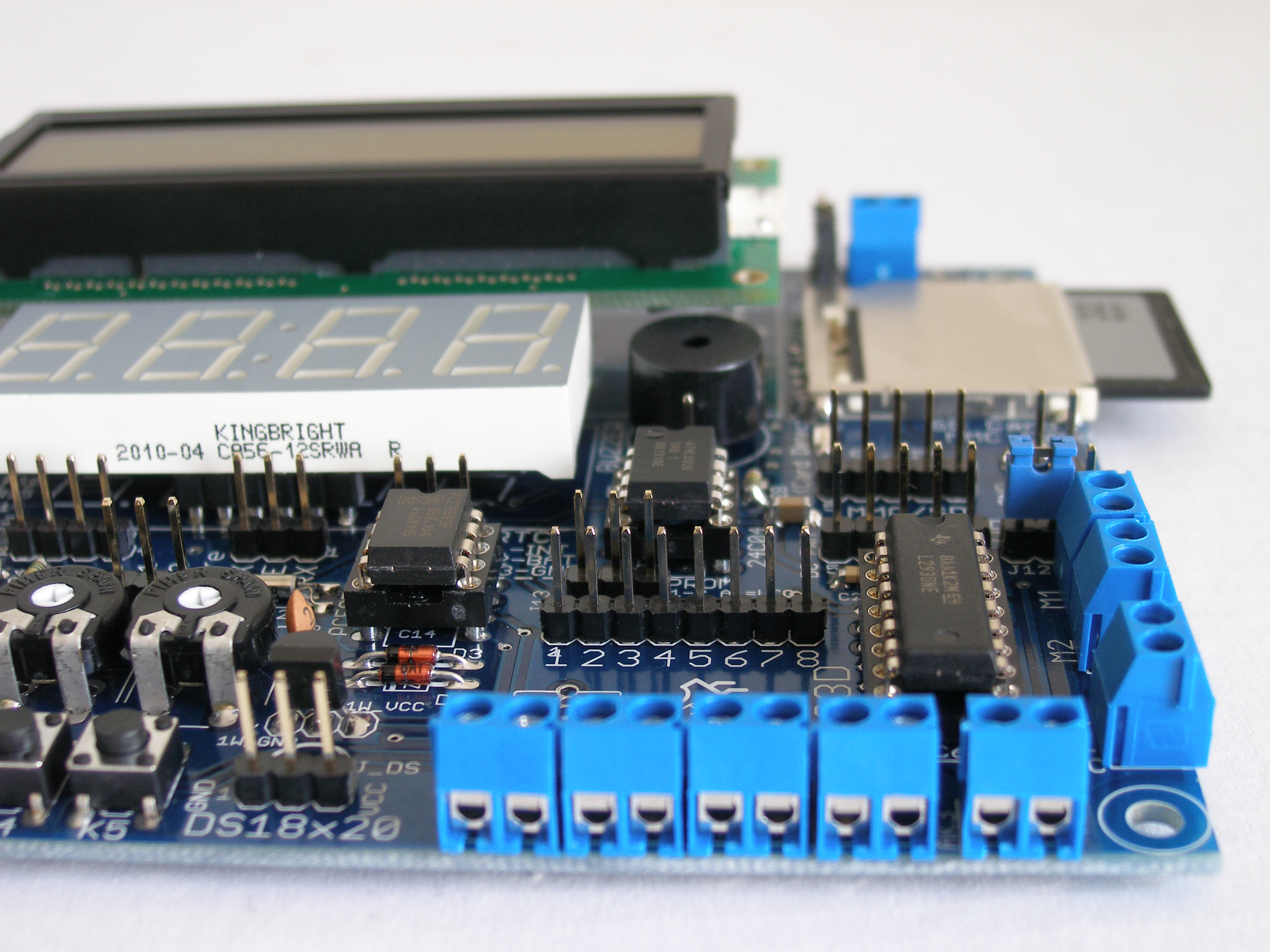
Final result:
Link to original thread – Własna płytka testowa - AVR - dużo możliwości/zastosowań