Continue to Site

Welcome to EDAboard.com

Welcome to our site! EDAboard.com is an international Electronics Discussion Forum focused on EDA software, circuits, schematics, books, theory, papers, asic, pld, 8051, DSP, Network, RF, Analog Design, PCB, Service Manuals... and a whole lot more! To participate you need to register. Registration is free. Click here to register now.

avago Lna oscillation when using a coupler at the input

Status
Not open for further replies.

xonatan

Newbie level 3
Joined
Jan 18, 2010
Messages
4
Helped
0
Reputation
0
Reaction score
0
Trophy points
1,281
Location
Wien
Activity points
1,334
Dear Friends

I made an RF LNA amplifier using Avago MGA-632P8 . The schematic and component values follow description in MGA-632P8 datasheet(). However, in order to match the amplifier to my work frequency, some values were adjusted using AWR microwave office.

Then, to test the proper operation of the circuit, I make a test board. I tested it alone and also connected to a LPF at the output and a BPF at the input. The result was positive, the expected gain, S11, S22, etc... in both situations ok.

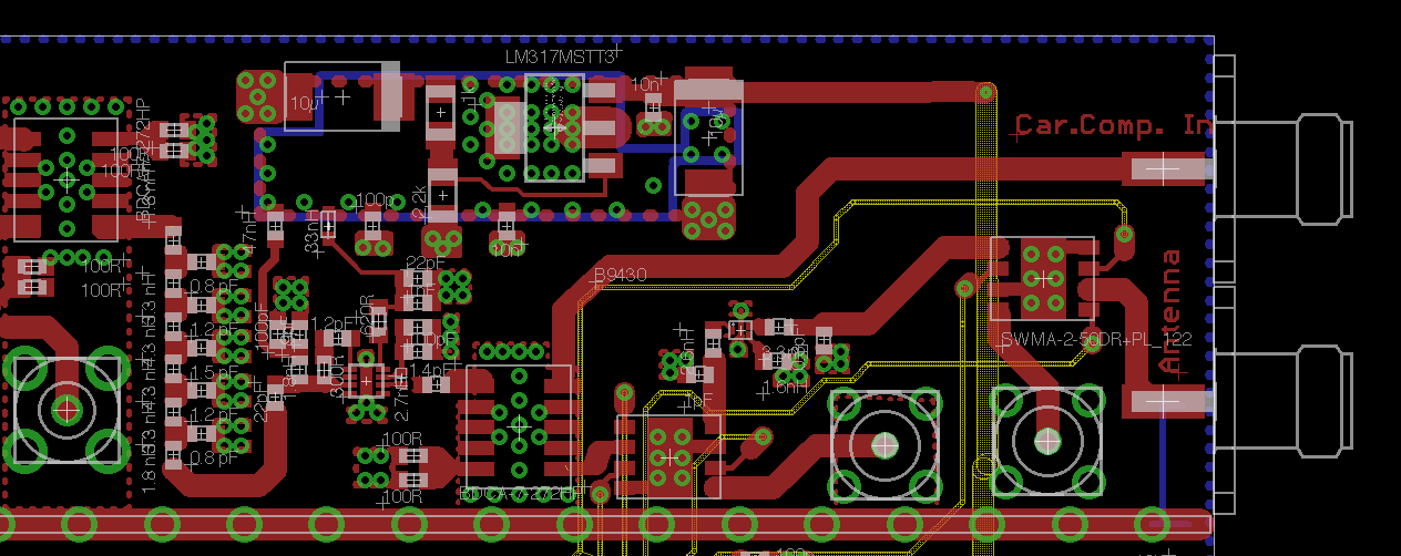
now, in my final circuit, I have the same chain as before but between the LNA and the BPF filter (LNA input) I placed a coupler to measure a coupled signal, BDCA1-7-33 from minicircuits (https://www.minicircuits.com/pdfs/BDCA1-7-33+.pdf) and a switch,SWMA-2-50DR+, (https://www.minicircuits.com/pdfs/SWMA-2-50DR+.pdf) to swap different BPF.

so, with this new board, when I measure the RF amplifier with no RF input, I find oscillation in around 4.3 GHz in its harmonics. I have tried to move some components around the amplifier, but the oscillation always occurs. Only it disappears when I replace the coupler by a 50ohms resistor. then the amplifier does not oscillate more.

some of you could help me to know why it seems this coupler (50ohms) is the cause for the oscillation?

Thank you very much for your help.

Regards,

Xonatan
 

If you post your application circuit, we can say something..
 

Thank you BigBoss for your answer! :)

Here I attach my layout circuit. From right to left there are: RF input (antenna), a switch which let me use an onboard BPF (you can see on the layout) or a external BPF (you can see only the ports). a switch again to go to the main path, a coupler, the LNA, a LPF and a second coupler which now is replaced by a 50 ohm resistor in order to find the LNA oscillation source.

Like I explained before, I have replaced and moved some devices in order to find the oscillation source. After some test, I could say my problem is when connect the first coupler (the one on the right, top view) to the LNA input. Why? because when I replace both couplers by a 50 ohm resistor (the LNA input is 50 ohm and the LNA output is the LPF and a 50 ohm resistor) the LNA does not oscillates. but, when I replace only the first coupler (with a 50 ohm resistor in its input, no RF signal) the LNA oscillates again.

I have tested others possible source like the supply voltage, biasing. But using a external supply voltage still the oscillation is there. Nevertheless, I make some test PCB to test the LNA, the LPF, the BPF. I connected all of them, and the result was the expected theoretically. The only way to produce the oscillation on the test PCB is connecting the output to the input. Of course then the LNA oscillates at the same frequency like my final circuit.

I am RF engineering student and I would like to know your opinion about my problem, and what you would do to fix this problem with, what I guess, my coupler problem.

If something is not understood, ask me i will try to explain again. Thank you for your help! :)


BigBoss said:
If you post your application circuit, we can say something..

The schematic is necessary to check your circuit.Nothing is understood from your PCB.
 

it is hard to understand in your layout.can you upload your shematic and mark which block in your layout?
 

yes you are right!

It is impossible to understand... For this reason, here is again my layout marking every block, and my schematic. I hope now it is better to understand.

thank you for your help!
 

Hello there:

I have also observed that some LNAs tend to oscillate when their input match is not exactly 50 Ohms. Better LNAs are usually more sensitive to input mismatch.
My advice is- if you see an oscillation upon connecting anything else but a 50-Ohm termination, the problem is certainly in that "anything else". Connect a matching circuit, at microwaves it can be a 50-Ohm line with piston or screw tuners, and adjust it so any oscillation stops.
This matching circuit may be narrow-band but another solution is to measure the impedance of anything you connect to your LNA input. Adjust its impedance to match 50 Ohms; then I expect there will be no oscillation.
If you have a spectrum analyzer capable to show an oscillation at ~ 4 GHz, I hope you have more good test equipment to measure and correct your device's match.
 
Do you terminate the other input ( test input )of the coupler when you don't use ??
 
Have you ever measured the impedance before C14?
 

Did you check the stability circles of the LNA ?

It sounds like your design is great for an "Ideal" 50 Ω input, but
once you connect the coupler (and it's preceding network) it sends
the LNA in to Oscilation, because that network in not a purely resistive load.
It Osc. at 4.3GHz? So is you circuit tuned for ~ 2.15GHz?
That is reasonable to have good a match at 2xFo in many designs.

You can try to change the 1.5pF cap on the input of the LNA see if that will
kill the Osc. maybe try to put a 1pF shunt cap between the coupler &LNA, of
course you will need to adjust the matching inductor too.

Good luck
 

have you tried changing the resistor R1 suggested for this LNA?In your case you have used 300 ohms. This device has sparameters for different values of R1, all under same bias conditions.

I ve checked K for all the different available sparameters and looks like it is pretty high for 4.3 GHz, where you have the oscilation. However, depending on the value for R1 you may find K can change between 18 and 27 @4.3 GHz.....(27 is the value using 91 ohms resistor for R1 position). Perhaps to have this set up can add some robustness against this problem.

I hope this helps.
 

Another thing I just spotted is the lack of vias under the package of the MGA-632 whereas in the manufacturers datasheet; it has many.

For ePHEMT technology, this could lead to excessive source inductance which in many cases drives to instability.
 

How about add a Isolator before the LNA? Although it maybe increase the NF about 0.3dB, but it help to stop self-oscillation.
 

Status
Not open for further replies.

Part and Inventory Search

Welcome to EDABoard.com

Sponsor

Back
Top