Continue to Site

Welcome to EDAboard.com

Welcome to our site! EDAboard.com is an international Electronics Discussion Forum focused on EDA software, circuits, schematics, books, theory, papers, asic, pld, 8051, DSP, Network, RF, Analog Design, PCB, Service Manuals... and a whole lot more! To participate you need to register. Registration is free. Click here to register now.

automatic room light controller

Status
Not open for further replies.

beckhamho

Junior Member level 1
Joined
Apr 15, 2010
Messages
16
Helped
0
Reputation
0
Reaction score
0
Trophy points
1,281
Activity points
1,411
Hi all,

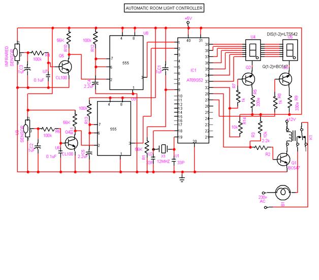
I have some question regarding this project's schematic.


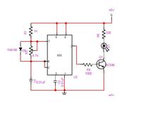
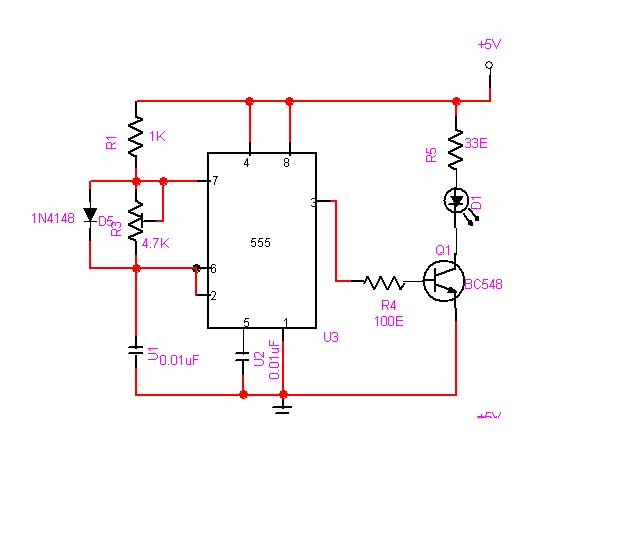
Basically the transmitter will emit a 38Khz signal and receive by the receiver.
The receiver will always in low stage when it received the 38khz signal from the transmitter. When there is a object obstructed the signal. The receiver will goes to high stage.
my question is what is the purpose of the 555timer at the receiver side?

thanks for the reply transmitter.jpg
 

when it receives the signal the base current will flow (as the transistor behave like a switch) this will trigger the 555 timer. After triggering 555 generate the output; this output is connected to the ucontroller; and it will decide what to do (according ro your programming).
 

hi Audioguru,

you said that "The collector of a transistor also has the received signal but it is inverted." mean that the signal feed into 555 timer is the inverted signal? And the output at pin3 is also the inverted signal? or the signal will be re-inverted back (same as the signal received by the receiver?
 

Why don't you look at a "common emitter transistor" in Google to see that it inverts the signal? Then when the IR beam is broken the output of the IR receiver IC goes high and the collector of the transistor goes low which triggers the 555 so its output goes high for its time duration.
The 555 is a timer. Its output high duration is much longer than the output high of the IR receiver IC.

Then look at the datasheet for the 555. The 555 is triggered when its pin 2 (the collector of the transistor) goes low, not high.
 

Hi Audioguru,

I had a major problem here. I couldn't get tsop1738 at my area. Can you please recommend any other receiver?

can i replace it with tsop1138 since the pin number are exactly the same with tsop1738.
Or tsop4838? the pin leg is difference.
Tsop1738: pin1=gnd,pin2=Vs,pin3=output
Tsop4838: Pin1=output,pin2=Gnd,pin3=Vs
Can i replace tsop1738 with tsop4838, just that i modified the schematic(due to the difference pin leg)?
 
Last edited:

The datasheets for the TSOP IR receiver ICs that you listed are shown as having a different number of 38kHz cycles recommended in each burst.
So simply do the recommended number of cycles in each burst.
 

Hi Audioguru,

For Tsop1738 it is 10cycle/bursts which is same with the Tsop4838.
The only difference is for tsop1738:After each burst which is between 10 cycles and 70
cycles a gap time of at least 14 cycles is neccessary.
Tsop4838:After each burst which is between 10 cycles and 70
cycles a gap time of at least 14 cycles is neccessary.

you said that "So simply do the recommended number of cycles in each burst."
how to design the number of cycle in each burst. Please help on this.
And how to check whether it is 10cycle in a burst?

Thanks again
 

ch burst."
how to design the number of cycle in each burst?
Use a second 555 (or use a dual called a 556) to turn the 38kHz 555 on and off to make the number of 38kHz cycles in each burst and to make the pause in between bursts.

how to check whether it is 10cycle in a burst?
Look at it on an oscilloscope.

Maybe you can do it digitally.
 

Hi Audioguru,

Can you provide any schematic to connect to another 555?

Does it necessary to care about the burst length and the off time?
from the original circuit, its does not use another 555 to on and off the IR transmitter.
what happen if i ignore the burst length and the on and off time?
the sensitivity and the range will reduced?

anyway to do it digitally?
thank you
 

Hi Audioguru,

Can you provide any schematic to connect to another 555?
Look at the datasheet for the 555 or ask your teacher to help you. It is simple.

Does it necessary to care about the burst length and the off time?
Your English is horrible. I think you are asking if the burst length and pause between bursts is important. Look at the datasheet of the IR receiver IC or ask your teacher.

from the original circuit, its does not use another 555 to on and off the IR transmitter.
There are thousands of schematics on the internet done wrong that do not work.

what happen if i ignore the burst length and the on and off time?
the sensitivity and the range will reduced?
I told you in my first post in this thread and the datasheet for the IR receiver tells you.
The IR receiver is designed to detect data (bursts of pulses) from a remote control transmitter and to reduce its gain with its AGC when it receives continuous 38kHz IR pulses (interference) from a compact fluorescent light bulb. When it reduces its gain then the sensitivity will be very low and range will be very short.

anyway to do it digitally?
Probably. Think about it then design a circuit to do it. But most people simply use a microcontroller that is programmed to do it.
You can buy an IR remote controlled light dimmer in a home improvements store.
 

Hi Audioguru,

I got the idea now.
The pause between the burst need to be 10 to 70cycles
if i choose 35cycle, the pause will be (1/38Khz * 35) = 0.92ms
1/0.92m = 1.1Khz.
So i need to construct another 555 that produce 1.1KHz. Am i correct?
After that the output(pin3) of the 555 that produce 1.1Khz will be connected to which pin of the 1st 555? To reset pin?
thanks
 

Hi Audioguru,

I had redesigned another value for R1,R2 and C

The burst length is about 615uS
and the pause is about 568uS.

I think both values passed the requirement stated in the TSOP datasheet.
How do you think?
my doubt is that the value for burst length too large?
thanks
 

You will have about 23 pulses of 38kHz in 615us which is fine.
The pause will have a duration of about 22 pulses which is also fine.
 

Hi Audioguru,

So the modulating signal can be check at the pin3 of the 555timer?
and also can be check at collector of the transistor. Just that the signal is inverted?
thanks
 

Status
Not open for further replies.

Part and Inventory Search

Welcome to EDABoard.com

Sponsor

Back
Top