Continue to Site

Welcome to EDAboard.com

Welcome to our site! EDAboard.com is an international Electronics Discussion Forum focused on EDA software, circuits, schematics, books, theory, papers, asic, pld, 8051, DSP, Network, RF, Analog Design, PCB, Service Manuals... and a whole lot more! To participate you need to register. Registration is free. Click here to register now.

Auto switch circuit for bike light?

Status
Not open for further replies.

piesoup

Newbie level 3
Joined
Aug 14, 2009
Messages
3
Helped
0
Reputation
0
Reaction score
0
Trophy points
1,281
Location
UK
Activity points
1,332
on off switch circuit

Hello

As this is my first post I'll introduce myself. I am an Aircraft Technician in the Army and am involved in the mech side of life. However I have a basic understanding of electrics and electronic circuits. ie. Ohm's Law, power etc. I design and build high power LED bicycle lights using CREE LEDs. This is the forum we usually hang out in MTBR DIY Lights
IMG_0959.jpg


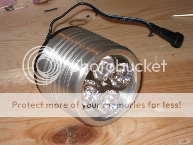
As you will know, these LEDs, when driven at their upper limit require a great deal of heatsinking to keep them cool. I use the air rushing over the aluminium casing to keep them cool. However, when we stop riding we have to remember to turn the light down or off so it doesnt overheat. If it isnt turned down that isnt a problem for the LEDs as the constant current driver that I use has a temp sensing function and will dim the lights when they hit the preset temp. Usually 50 degrees C. Now that presents problem as it will only allow the light to retuen to max when the temp has dropped by 5 degrees.

Now for my idea! I want some electronic wizardary to sense when the bike has stopped and dim or turn off the light. And then turn it on again as soon as the bike starts to move.
I have thought about using the wired sensor that cycle computers use to measure wheel speed. A simple magnet on the wheel spoke to a switch.

The driver utilises a single momentary NO switch to turn on and off and cycle between modes. Here it is **broken link removed**
All the *.flex drivers use the same UI. In short, a single click ( < 0.3 sec ) turns On and a press > 4 sec will turn it off from any level. (It will cycle from level 5 down to level 1 then 2 sec later turn off.)

So, is there something I can build to put in parallel with the existing switch to give me auto off and on? Like a micro controller of sorts? A circuit that when it stops receiving a signal from the front wheel, it latches a switch for 4 seconds, turning off the light. Then when it receives a signal from the front wheel that the bike is moving again, the switch is latched for 0.3 sec, turning my light on again. Anything out there that can do this?

I have tried to search but there is nothing to be found. Could kind person help out and point me in the right direction!

Thank you for reading this far, I hope it all makes sense!

Andrew
 

auto switch circuite

Type general family of circuit you need is called a missing pulse detector. Below is a link to an example. This can be done with existing timer or oscillator chips, like the 555. Or, as you mentioned, it can be done using a small microcontroller. Using an exisiting multivibrator chip or timer is usually faster to design. However, the microcontroller approach can be more closely tailored to any desired special features.

http://www.ecelab.com/circuit-miss-pulse-det.htm

The relay to control the lamp should be wired in series with the standard on/off switch. From a dead stop, both the on/off switch must be ON and you must have pedaled enough revolutions to disable the missing pulse detector for the lamp to come on.
 

    piesoup

    Points: 2
    Helpful Answer Positive Rating
existing bike lights

I think you may have hit the solution yourself without realising it.

The problem is overheating when you don't have forced air cooling, combined with the heat transfer delay associated with the mass of the aluminium.

Why not use a small 'al fresco' heated sensor in the same air stream so it models the large LED enclosure but has a much faster reaction time. You could use a small thermistor with enough current passing through it to keep it warm as the sensor. If the airflow cools it down, its value will change and this could control your LED current.

It should be much simpler than looking for motion and done correctly it can protect against the problem of ambient temperature and things inadvertently restricting the air flow.

Brian.
 

    piesoup

    Points: 2
    Helpful Answer Positive Rating
how to make an auto off circuit

Hi Betwix
Thanks for your reply. The constant current driver installed in the light, thermally bonded with Arctic Silver to the 'firewall' opposite the LEDs monitors their temp. If they go past a preset temp, 50C, it will automatically dim them. However after the LEDs have cooled 5C the light can be manually cycled up to max again. This cooling is what takes time and is the cause of my half thougt out idea! Usually I wil stop at the top of a large descent to check pads etc, then the light will dim because of the heat after about 60sec. I have to then pedal around and wait for the light to cool, not easy if it is on singletrack. Ideally I'd like the light to shut off automatically as soon as I stop.
A few of the guys have got a thermistor installed but that still takes a while to cool. I understand about having the sensor 'al fresco', but will it react as soon as I start to move off? You're right about the heat transfer due to the mass of the aluminium, got to get the housing just right!

Banjo, I remember the 555 from when we did a few months 'try out' of electronics at school many moons ago! I sort of understand that circuit....
The input, must it be +5v? If so, can I use the same 5v that is powering the circuit? ie. switched with the sensor on the wheel?
And how can I use the output to latch a switch for 4 sec when it stops receiving a pulse and to quickly make the switch for 0.3sec when it receives a pulse when I set off.

The constant current driver is permantly connected to the battery, regardless if the light is on or off. A mom switch on the driver switches the light on or off without disconnecting power to the driver. So I would have to put the new 555 controlled switch in parallel with my existing mom switch. If the power from the battery is switched, the light will not turn on as it needs a 0.3 sec input from the mom switch.

Thanks !
 

high and low switch for llight for bike

Hi Piesoup.

The thermistor I'm talking about isn't measuring the LED temperature, it is in free air so it gets cooled by the passing air flow.

A thermistor will react in a fraction of a second if used properly. A small one with enough current through it to warm it up will be very sensitive to air flowing past it. There used to be a design for detecting air currents in houses so they could be draught proofed which was nothing more than a modified flashlight bulb and test meter. A wire cage was soldered to the screw thread so it protected the filament then the bulb was crushed in a vice so the glass cracked and could be removed. A small current (a few mA) was passed through the filament and the current measured. A crude but very effective thermistor was made for almost zero cost. Any air flow around the filament made its resistance drop dramatically.

The bulb would of course be vulnerable to the environment and if your cycling is like mine, would involve it being wet most of the time (I'm in Wales!) but a small bead thermistor would work just as well and be 'cyclist proof'.

If you go the motion detecting route, the simplest solution would probably to use the spokes to interrupt an IR light beam. Fix an IR LED to one fork, a sensor to the other and feed the sensor into a timer. I would probably use a PIC10F202 which costs about 40p. The principle is that you keep a timer running which counts up to some large number, if it reaches it, you drop your LED current. Normally, the chopped IR beam would reset the counter to zero each time so the LED stays at full power. You can do it with a simple counter circuit but PICs are cheaper and you can easily cater for situations where for example, you stop with a spoke blocking the beam.

Brian.
 

make electronic circuits for bike

Hi Brian
I have sent you an email!
 

bike electronic circuit

I'm a cyclist too. I commute to work on a bicycle.

Would direct sensing the temperature of the aluminum block work? A thermistor (or a simple silicon temperature sensor such as LM35) with a comparator could provide a digital overheat signal, which can be used to cut or reduce the power to the LEDs. Essentially, the delay between the end of the ride and the turn off of the lights would be the thermal lag in the heat sink.
 

how are lights turned on and off on a bike

I think Piesoup is away for a few days but I'm sure he will be back soon.

The problem with the temperature sensing is the ambient (air) temperature which can be very different from place to place. Here, for example, it isn't uncommon for the air to be below 0C in winter and 30C+ in summer. You also have to take into account the effect of direct sunshine on the light itself which is of course in an exposed position. That isn't to say there shouldn't be some overheat protection to protect the LEDS as well, that would be essential to prolong their lives.

I have copied a private email I sent to Piesoup below, it contains nothing of a personal nature but suggests a cheap alternative to the purely temperature based approach. I have used a similar principle to control dynamic braking on aircraft landing gear so the pulse counting to PWM principle definitely works.

------ copy of email -------

I think you may be taking a more complicated route than necessary. Can you describe in more detail, your existing design to me please.

If I understand you, the lights will only operate when the bike is in motion and your 'missing pulse' detector is to detect that motion by monitoring the rotation of one of the wheels. If I'm right, the light will turn off when you stop, which is not a good idea, especially at road junctions.

Wouldn't it be better to control the LED current so it is reduced when stationary but some residual light is left there for safety and visibility?

Again, if I understand your intention, may I suggest an alternative way which uses few components and is more versatile in the way it controls the LED current: there are a multitude of PIC processors which cost about the same as a single 555 timer and are also capable of performing the same function. They have the advantage of being able to detect pulse edges rather than than just presence so they can tell the difference between a changing input and a static one. This is important because your motion detector could produce a high signal or a low signal when the wheel is stationary. They can also produce (by using PWM) analogue voltages which could be used to control the LED current. You even get a few spare input and output pins thrown in for other purposes.

I envisage the light running at full power when you are moving, dropping over say 30 seconds to a lower level when you stop and switching off completely after say 2 minutes on the assumption your ride is over. If the LEDs get very hot you could use a temperature sensor input to control the current using the same drive signal.

If you haven't used PIC devices before, they are incredibly easy to program and some (I think a 12F683 would be ideal for this task) include all the support circuitry you need and only draw a few microamps in a standby state. If practical, you could use a reluctance sensor to monitor motion as they draw no current and you could even eliminate the on/off switch completely!

------ end of copy of email -------

Its an interesting topic, not only for cyclists but anyone else designing similar control systems where available power is variable and very limited.

Brian.
 

light small switch circuit

Check this out:

**broken link removed**
 

existing cycle lights

Wait until Piesoup returns.

That link requires you take out a subscription to get 'download credits' and although I like Elektor magazine, I'm not prepared to pay while I'm giving free help anyway.

I already have in mind a design which incorporates the LED voltage boost circuit and PWM controller for the brightness, and motion detecting as well. I don't think the specified 1 minute shut-off is very good in the Elektor description anyway, consider how long you could be stopped at a traffic junction, would you like your lights to go out automatically ??

I'm waiting on Piesoup to give me more information on the existing LED wiring before developing it further.

Brian.
 

Status
Not open for further replies.

Part and Inventory Search

Welcome to EDABoard.com

Sponsor

Back
Top