mdanh2002
Newbie level 4
Hi,
I am trying to build Tetsuo Kogawa's simple TV transmitter with audio following the instruction here: https://anarchy.translocal.jp/microtv/how_to_advancedTVTX_p0.html (Before this I have tried, successfully, to build the silent version of the transmitter with no audio at https://anarchy.translocal.jp/microtv/howtotvtx.html and the circuit works upon first power on).
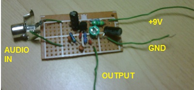
This time, I started with building the audio section of the circuit (https://anarchy.translocal.jp/microtv/how_to_advancedTVTX_p2.html), which is essentially an LC oscillator @ 5.5MHz (for PAL B/G audio subcarrier used in Singapore). I do not have the 2SC transistor so I replaced with a 2N3904 instead. I also removed the 1K variable resistor that attenuates the audio input and connects the audio from my VCR directly to the 10uF capacitor. I build everything on a stripboard. I am using a 47uH resistor-like inductor with a 35pF trimmer capacitor. Using the formula L*C*(2*pi*f)^2 = 1, I estimated the frequency to be around 3MHz - 11MHz.
However, upon completion of the audio section (without the main section), I used my oscilloscope to check the output (after the 10pF capacitor). The circuit does not oscillate at 5.5Mhz no matter how I adjust the trimmer capacitor. The oscilloscope frequency counter is random. In fact, the output waveform resembles the input audio, although with much lower magnitude.
Any advice on what might be the problem? I seriously do not think there are any connections issues - this is my 3rd attempt, all with same results.
Thanks in advance")
I attached pictures of my build (front and back) on a veroboard.

I am trying to build Tetsuo Kogawa's simple TV transmitter with audio following the instruction here: https://anarchy.translocal.jp/microtv/how_to_advancedTVTX_p0.html (Before this I have tried, successfully, to build the silent version of the transmitter with no audio at https://anarchy.translocal.jp/microtv/howtotvtx.html and the circuit works upon first power on).
This time, I started with building the audio section of the circuit (https://anarchy.translocal.jp/microtv/how_to_advancedTVTX_p2.html), which is essentially an LC oscillator @ 5.5MHz (for PAL B/G audio subcarrier used in Singapore). I do not have the 2SC transistor so I replaced with a 2N3904 instead. I also removed the 1K variable resistor that attenuates the audio input and connects the audio from my VCR directly to the 10uF capacitor. I build everything on a stripboard. I am using a 47uH resistor-like inductor with a 35pF trimmer capacitor. Using the formula L*C*(2*pi*f)^2 = 1, I estimated the frequency to be around 3MHz - 11MHz.
However, upon completion of the audio section (without the main section), I used my oscilloscope to check the output (after the 10pF capacitor). The circuit does not oscillate at 5.5Mhz no matter how I adjust the trimmer capacitor. The oscilloscope frequency counter is random. In fact, the output waveform resembles the input audio, although with much lower magnitude.
Any advice on what might be the problem? I seriously do not think there are any connections issues - this is my 3rd attempt, all with same results.
Thanks in advance
I attached pictures of my build (front and back) on a veroboard.