bob808
Newbie level 3
Hello all,
I got a cheap headlamp with a powerful LED and the trouble is that the driver inside is real bad. On High mode the cheap mosfet gets at over 100 degrees C.
So I decided to build myself a proper driver board.
I want to have 3 modes on it. Low (moonlight mode), Medium (1.4A) and High(3A).
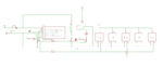
I didn't want to mess with pwm and so I went this route: for the moonlight mode I use 1x AMC7135 current sink at 350mA. For the Medium mode I have another arrangement of 4x AMC7135 totalling 1.4A. And for the full output I'm using a PSMN0R9-25YLC N-Channel Mosfet.
These three modes need to be triggered from the pins of the Attiny13A.
Another input pin is to be used for the pushbutton.
Basically I'm looking to program the Attiny13A in this sequence. On each press of the button to cycle High the next output pin, and low the others. After I cycle through all 3 output pins, to pull low all of them.
I managed to adapt some pieces of software to flash all of them at once, or to flash each one. But can't figure out how to use the button and cycle through all of them.
I also provisioned on the board a sense pin for the battery voltage, so I maybe implement a shut-down feature when the voltage is below a threshold. But right now that is not important.
Right now the pins are as follow:
PB0 - Moonlight (1x AMC7135)
PB1 - Mosfet (full power - 3A)
PB2 - input from battery with voltage divider
PB3 - Button input
PB4 - Half output (4x AMC7135 1.4A)
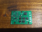
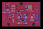
This is the way I designed my pcb, can't change it as I've already soldered everything apart from the mcu.
I attached a photo of the pcb. If there's anyone who wants the pcb files I can provide them for free")
I find this setup nice as it doesn't messes with PWM. And has about everything that's needed (low, mid, high, battery monitoring).
Also I provisioned the board for the button to be pull up and pull down (smd resistor pads that can be used as jumper pads). There's a status led for when it's on etc.
Now, where do I look so I can manage to figure out how to first cycle through the PB0 - PB4 - PB1 pins (as output) and then pull all of them down (and enter sleep mode after all pins are pulled down to save battery when I don't use the headlamp) ?
I tried to find some help on budgetlightforum.com but received none. Probably because my project is open and there's enough people selling their stuff over there so ... yeah.
Basically this is a XM-L2 3A driver used for the cheap headlamps found on ebay. Fits in place of the crappy original ones.
Any help is appreciated.
Thank you.
I got a cheap headlamp with a powerful LED and the trouble is that the driver inside is real bad. On High mode the cheap mosfet gets at over 100 degrees C.
So I decided to build myself a proper driver board.
I want to have 3 modes on it. Low (moonlight mode), Medium (1.4A) and High(3A).
I didn't want to mess with pwm and so I went this route: for the moonlight mode I use 1x AMC7135 current sink at 350mA. For the Medium mode I have another arrangement of 4x AMC7135 totalling 1.4A. And for the full output I'm using a PSMN0R9-25YLC N-Channel Mosfet.
These three modes need to be triggered from the pins of the Attiny13A.
Another input pin is to be used for the pushbutton.
Basically I'm looking to program the Attiny13A in this sequence. On each press of the button to cycle High the next output pin, and low the others. After I cycle through all 3 output pins, to pull low all of them.
I managed to adapt some pieces of software to flash all of them at once, or to flash each one. But can't figure out how to use the button and cycle through all of them.
I also provisioned on the board a sense pin for the battery voltage, so I maybe implement a shut-down feature when the voltage is below a threshold. But right now that is not important.
Right now the pins are as follow:
PB0 - Moonlight (1x AMC7135)
PB1 - Mosfet (full power - 3A)
PB2 - input from battery with voltage divider
PB3 - Button input
PB4 - Half output (4x AMC7135 1.4A)
This is the way I designed my pcb, can't change it as I've already soldered everything apart from the mcu.
I attached a photo of the pcb. If there's anyone who wants the pcb files I can provide them for free
I find this setup nice as it doesn't messes with PWM. And has about everything that's needed (low, mid, high, battery monitoring).
Also I provisioned the board for the button to be pull up and pull down (smd resistor pads that can be used as jumper pads). There's a status led for when it's on etc.
Now, where do I look so I can manage to figure out how to first cycle through the PB0 - PB4 - PB1 pins (as output) and then pull all of them down (and enter sleep mode after all pins are pulled down to save battery when I don't use the headlamp) ?
I tried to find some help on budgetlightforum.com but received none. Probably because my project is open and there's enough people selling their stuff over there so ... yeah.
Basically this is a XM-L2 3A driver used for the cheap headlamps found on ebay. Fits in place of the crappy original ones.
Any help is appreciated.
Thank you.