Continue to Site

Welcome to EDAboard.com

Welcome to our site! EDAboard.com is an international Electronics Discussion Forum focused on EDA software, circuits, schematics, books, theory, papers, asic, pld, 8051, DSP, Network, RF, Analog Design, PCB, Service Manuals... and a whole lot more! To participate you need to register. Registration is free. Click here to register now.

attenuator resistor formulas ?

Status
Not open for further replies.

fran1942

Junior Member level 3
Joined
Mar 16, 2012
Messages
30
Helped
0
Reputation
0
Reaction score
0
Trophy points
1,286
Activity points
1,520
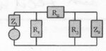
Hello, I am trying to work out the resistor values for an 'O' attenuator.
I am using the attached formula to work out resistor 3's value.
My values to insert into this formula are:

Input impedance (Z1) = 50 Ohm
Load impedance (Z2) = 600 Ohm
a =1.995

However when I substitute these figures I am getting a negative number result.
Is this correct ? I mean if you get a negative result, do you just make it positive and use that for your resistor value ?

Thanks for any help. form.jpg
 

Attachments

  • formula.jpg
    formula.jpg
    30 KB · Views: 101
Last edited:

I'm not familiar with the 'O' attenuator. Can you post a schematic?
 
yes, here is it. Thanks for your help.

So, when I do the calculation for R3 as per my attached formula, I get a negative number. Obviously I cannot have a negative Ohm resistor, so how do I interpret this outcome ?
Thank you for any insight.form.jpg

pad.jpg
 

Attachments

  • oatt.jpg
    oatt.jpg
    93.3 KB · Views: 83
Last edited:

What you're showing is a standard **broken link removed** attenuator (because it looks like the Greek letter, pi). An 'O' pad is also called a balanced PI pad, and consists of 4 resistors in a square. Those are generally installed on balanced transmission lines and can be analyzed like a standard (unbalanced) PI pad by halving the shunt resistance values and halving the voltages.

I haven't run across an unequally terminated PI pad attenuator before, but I'm sure they're out there. If you can suffer the insertion loss hit, you can keep going down this path. The simplest way to find an answer for me would be to simulate the circuit in something like ADS or MWO and setup an optimization simulation to minimize in return loss and insertion loss. If you can find the derivation of those equations in the textbook, the assumptions for the equations will often tell you what setup criterion you're violating (perhaps you need to swap Z1 and Z2?).

The more RF-efficient method would be to use a matching circuit comprised of L's and C's to convert from 50 ohms to 600 ohms. A two-part ("L") match can be found quickly for a single frequency/narrowband system. For wider bandwidths, you can scale up to multiple parts, but tuning the design becomes much more time intensive (but can also be done with an optimizer to perform many iterations very quickly).
 
There's a few problems here. The picture you showed in post 3 is a PI attenuator, not an O attenuator. Your formula for R3 is correct for a PI attenuator or an O attenuator but your formula for R1 is only correct for a T attenuator.

Most importantly, for Z1 = 50 Ohms and Z2 = 600 Ohms, the minimum attenuation is about 16.63dB, so "a" must be greater than about 6.78.

This page gives the formulas for different attenuator types: https://www.giangrandi.ch/electronics/attenuators/attenuators.shtml
 
Status
Not open for further replies.

Part and Inventory Search

Welcome to EDABoard.com

Sponsor

Back
Top