Continue to Site

Welcome to EDAboard.com

Welcome to our site! EDAboard.com is an international Electronics Discussion Forum focused on EDA software, circuits, schematics, books, theory, papers, asic, pld, 8051, DSP, Network, RF, Analog Design, PCB, Service Manuals... and a whole lot more! To participate you need to register. Registration is free. Click here to register now.

Attenuator for spectrum analyser ??

Status
Not open for further replies.

sajeesh_elayath

Junior Member level 1
Joined
May 12, 2007
Messages
18
Helped
0
Reputation
0
Reaction score
0
Trophy points
1,281
Activity points
1,402
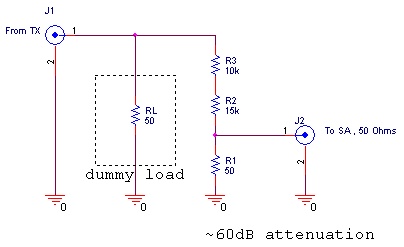
How can I interface my equipment delivering an RF power of around 100W, to a hand held spectrum analyser(Rohde & Schwarz FSH Series)which is only having a power handling capacity of 100mW. Frequency range is around 50Mhz.Can anybody suggest an appropriate attenuator ?
 

Try
http://www.bird-electronic.com/products/product.aspx?id=410
**broken link removed**

or Google - RF Attenuator 100 Watts

If you need something in a hurry you could always make one. A long length of lossy coax, RG174 or similar will waste enough power for you to be able to use conventional resistors and or lower power pads. Frequency response will be very poor though.
 

Normally you do NOT put a 100 watt attenuator in front of a spectrum analyzer. If something bad happened to the attenuator, you would fry the analyzer.

A more standard way would be to insert a 30 dB high power directional coupler (high power in that it is designed to not arc over), and maybe a 20 dB low power attenuator after that before the spectrum analyzer.
 

Use a 50 Ohm dummy load rated for 100W or above.
In paralel with the dummy load connect a resistor voltage divider, with R1=50 Ohm, like in the schematic.
This gives about 60dB of attenuation, and ensures good termination for the TX, since the big resistor value doesnt significantly load the dummy load. Also the spectrum analyser is feeded from 50 Ohm impedance. You need to use 0.5W metal film resistors for R1, R2, R3 and minimize parasitic capacitance at the connections. Build it "in the air", in between the connectors with very short terminal leads. I think it will work to HF and low VHF frequencies, but above you need a standard attenuator.

For about 40dB attenuation the attenuation and impedances will be a little imprecise; use R2=1k5, R3=1k, rated for 5W and non inductive.

99_1183724234.jpg
 

Status
Not open for further replies.

Part and Inventory Search

Welcome to EDABoard.com

Sponsor

Back
Top