Continue to Site

Welcome to EDAboard.com

Welcome to our site! EDAboard.com is an international Electronics Discussion Forum focused on EDA software, circuits, schematics, books, theory, papers, asic, pld, 8051, DSP, Network, RF, Analog Design, PCB, Service Manuals... and a whole lot more! To participate you need to register. Registration is free. Click here to register now.

[SOLVED] Attenuating Buffer Circuit

Status
Not open for further replies.

EltonBrasil

Junior Member level 3
Joined
Oct 21, 2019
Messages
29
Helped
0
Reputation
0
Reaction score
0
Trophy points
1
Location
Columbus, Ohio, USA
Activity points
256
Hi Everyone,

I have designed a NFC system in which I can have around 100 V on the input antenna. So I need to attenuate the antenna signals (in terms of mV) before feeding them back to the reader module as well as keeping the antenna's resonance circuit quality factor. Hence, I would like to know an attenuating buffer circuit for my application.

Many thanks in advance.
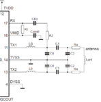
 

Most NFC and 13.56 MHz RFID chips are connecting the coil directly by means of a LC network. The Rx signal is usually tapped at the low voltage side of the matching network, where you have a < 10V signal level. There also no reason to attenuate the Rx signal down to mV.

rfid.PNG
 
Most NFC and 13.56 MHz RFID chips are connecting the coil directly by means of a LC network. The Rx signal is usually tapped at the low voltage side of the matching network, where you have a < 10V signal level. There also no reason to attenuate the Rx signal down to mV.

View attachment 156967

Sure. As you know there is communication between the reader and tag by an antenna. So when I need to receive the signal from the tag it will be high voltage, because my system can generate over 90 V to the antenna. It is high enough to blow up the reader. Are you with me? Thanks much for you quick reply.
 

You should apply circuit analysis and determine the individual node voltage levels. High voltage is only at the antenna side of the network (across C2). The shown application circuit is from NXP, you can also review design guides from other manufacturers.
 
TX and RX coils are part of resonant circuits, using series or parallel capacitors for doing this resonance.
If you de-tune the RX resonant circuit [identifying and changing the value of the resonant capacitor(s)] you may get lower voltage at the input of the reader module.
 
Status
Not open for further replies.

Part and Inventory Search

Welcome to EDABoard.com

Sponsor

Back
Top