roiberts
Junior Member level 1
Dear Forum
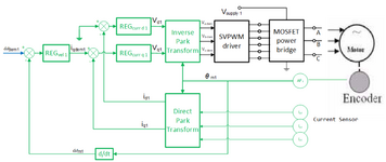
we have a asincronous motor connect to a SWPWM ,and with a encoder that read the angle.
The motor is in a closed loop, controlling the speed; the loop is the tipical composition i find
in lecterature named I.F.O.C..Schematic is in the figure I upload.
All math and block are realized via a DSP.
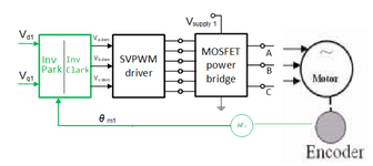
Before close the loop, i did test in open loop..
I used only 3 block,from the inverse park to motor. The input are Vd,Vq and Angle
(al set in my software..no from encoder or loop).
With this 3 input variable, I forced in my algoritm:
-Vq=0.1
-Vd=0
-Angle teta= N poits fix in time
-Result_1:-
I noted that if I set a Angle to a certain value, the rotor goes in a position,and
stay there. Increasing the angle, rotor move in this new angle.
If I put angle in a timer, rotor turn.
-Result_2:-
Increasing Vq dont change the rotor position.
What i dont understand is why rotor stay fix, if angle is fix . Equation says that Vq
create a tourque ,so, motor must rotate alwais.
So question are:
-Why rotor dont continue to move when i set a fix angle?
-If motor stay fix in such angle, and changing Vq dont change the rotor, how
Vq can change speed or position in closed loop ?
Thanks for your time and reply in this long question.
Roberto
we have a asincronous motor connect to a SWPWM ,and with a encoder that read the angle.
The motor is in a closed loop, controlling the speed; the loop is the tipical composition i find
in lecterature named I.F.O.C..Schematic is in the figure I upload.
All math and block are realized via a DSP.
Before close the loop, i did test in open loop..
I used only 3 block,from the inverse park to motor. The input are Vd,Vq and Angle
(al set in my software..no from encoder or loop).
With this 3 input variable, I forced in my algoritm:
-Vq=0.1
-Vd=0
-Angle teta= N poits fix in time
-Result_1:-
I noted that if I set a Angle to a certain value, the rotor goes in a position,and
stay there. Increasing the angle, rotor move in this new angle.
If I put angle in a timer, rotor turn.
-Result_2:-
Increasing Vq dont change the rotor position.
What i dont understand is why rotor stay fix, if angle is fix . Equation says that Vq
create a tourque ,so, motor must rotate alwais.
So question are:
-Why rotor dont continue to move when i set a fix angle?
-If motor stay fix in such angle, and changing Vq dont change the rotor, how
Vq can change speed or position in closed loop ?
Thanks for your time and reply in this long question.
Roberto