Continue to Site

Welcome to EDAboard.com

Welcome to our site! EDAboard.com is an international Electronics Discussion Forum focused on EDA software, circuits, schematics, books, theory, papers, asic, pld, 8051, DSP, Network, RF, Analog Design, PCB, Service Manuals... and a whole lot more! To participate you need to register. Registration is free. Click here to register now.

[SOLVED] ARM LPC2148 ADC Interfacing Problem?

Status
Not open for further replies.

xpress_embedo

Advanced Member level 4
Joined
Jul 5, 2011
Messages
1,154
Helped
161
Reputation
396
Reaction score
189
Trophy points
1,353
Location
India
Activity points
10,591
Hello!! Everyone i am new to ARM Micro-controller's, few months back purchased a Development Board having LPC2148 Micro-Controller.

I did Lcd Interfacing, UART and led also, but having some problem with ADC Interfacing.

Here is the Circuit for that.
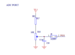
ADC.PNG

But its not working, LCD is working fine, please help me, here is my code


Code C - [expand]
1
2
3
4
5
6
7
8
9
10
11
12
13
14
15
16
17
18
19
20
21
22
23
24
25
26
27
28
29
30
31
32
33
34
35
36
37
38
39
40
41
42
43
44
45
46
47
48
49
50
51
52
53
54
55
56
57
58
59
60
61
62
63
64
65
66
67
68
69
70
71
72
73
74
75
76
77
78
79
80
81
82
83
84
85
86
87
88
89
90
91
92
93
94
95
96
97
98
99
100
101
102
103
104
105
106
107
108
109
110
111
112
113
114
115
116
117
118
119
120
121
122
123
124
125
126
127
128
129
130
131
132
133
134
135
136
137
138
139
140
141
142
143
144
145
146
147
148
149
150
151
152
153
154
155
156
157
158
159
160
161
162
163
164
165
166
167
168
169
170
#include <LPC214X.H>
 
/**********LCD Pin Configuration**********/
#define EN 19
#define RS 17
#define RW 18
//These all are connected on Port-1 of Controller, so make sure before using IOSET and IOCLR Functions
/*****************************************/
 
/***********FUNCTION PROTOTYPE***********/
void ADC_Init(void);
unsigned int Read_ADC(void);
void Delay(unsigned long value);
void Write_Cmd(unsigned int value);
void Write_Data(unsigned int value);
void Lcd_Init(void);                        //Initialize Lcd Module
void Lcd_Write(unsigned int value);
void Lcd_Cmd(unsigned int value);
void Lcd_Write_Text(unsigned char*);
/****************************************/
 
int main()
{
    unsigned int adc_data;
    unsigned char ones,tens,hundreds,thousands;
    Lcd_Init();
    Delay(10000);
    Lcd_Write_Text("   WELCOME...");
    Delay(100000);
    Delay(100000);
    Lcd_Cmd(0xC0);
    Lcd_Write_Text(" LPC2148 DEVBRD");
    Delay(100000);
    Delay(100000);
    Delay(100000);
    Delay(100000);
    Delay(100000);
    Delay(100000);
    Delay(100000);
    Delay(100000);
    Lcd_Cmd(0x01);
    Lcd_Write_Text("ADC EXAMPLE");
    ADC_Init();
    Delay(100000);
    while(1)
    {
        adc_data = Read_ADC();
        ones = adc_data % 10;
        adc_data = adc_data / 10;
        tens = adc_data % 10;
        adc_data = adc_data / 10;
        hundreds = adc_data % 10;
        adc_data = adc_data / 10;
        thousands = adc_data % 10;
 
        Lcd_Cmd(0xC0);      //Second Row
        Lcd_Write(thousands | 0x30);
        Lcd_Write(hundreds | 0x30);
        Lcd_Write(tens | 0x30);
        Lcd_Write(ones | 0x30);
        Delay(100000);
        Delay(100000);
        Delay(100000);
        Delay(100000);
    }
}
 
/***********FUNCTION DEFINITION************/
 
void Delay(unsigned long value)
{
    while(value>0)
    {
        value--;
    }
}
void Lcd_Init(void)
{   
    IO1DIR |= 0x00FE0000;
    //Pins P1.17 to P.23 as Output Pin
    Delay(200000);
    Write_Cmd(0x30<<16);
    Delay(100000);
    Write_Cmd(0x30<<16);
    Delay(100000);
    Write_Cmd(0x30<<16);
    Delay(100000);
    Write_Cmd(0x20<<16);
    //These are the Commands for LCD Initialization in 4-Bit Mode
    Lcd_Cmd(0x01);
    Lcd_Cmd(0x06);
    Lcd_Cmd(0x0C);
    Lcd_Cmd(0x80);
}
 
void Write_Cmd(unsigned int value)
{
    //First of all Clear the LCD Data Pins
    IO1CLR |= 0x00F00000;
    //To Write RW = 0
    IO1CLR |= (1<<RW);
    //Write to Command Register RS = 0
    IO1CLR |= (1<<RS);
    //Write to Pins
    IO1SET |= 0x00F00000 & value;
    IO1SET |= (1<<EN);
    Delay(30000);
    IO1CLR |= (1<<EN);
}
 
void Write_Data(unsigned int value)
{
       //First of all Clear the LCD Data Pins
    IO1CLR |= 0x00F00000;
    //To Write RW = 0
    IO1CLR |= (1<<RW);
    //Write to Data Register RS = 1
    IO1SET |= (1<<RS);
    //Write to Pins
    IO1SET |= 0x00F00000 & value;
    IO1SET |= (1<<EN);
    Delay(30000);
    IO1CLR |= (1<<EN);
}
void Lcd_Cmd(unsigned int value)
{
    Write_Cmd(value<<16);
    Write_Cmd(value<<20);
}
void Lcd_Write(unsigned int value)
{
    Write_Data(value<<16);
    Write_Data(value<<20);
}
void Lcd_Write_Text(unsigned char *data)
{
    while(*data != '\0')
    {
        Lcd_Write(*data);
        data++;
        Delay(10000);
    }
}
void ADC_Init()
{
    PINSEL1 |= 0x01000000;      //Configure P0.28 as AD0.2
    AD0CR = 0x00200602;
    /*
    SEL = 0x02 as AD0.2 is Choosen
    CLKDIV = 0x06
    CLKS and BURST = 0x0 means that 11 Intruction Cycles used,resulting in 10-Bit Data
    And Don't Start the Conversion Now
    */
}
unsigned int Read_ADC()
{
    unsigned int adc_data;
    AD0CR |= 0x01000000;        //Start the ADC Conversion
    do
    {
        adc_data = AD0DR0;
    }while(!(adc_data & 0x80000000));
    //Wait untill the DONE bits Sets
    AD0CR &= 0xFE000000;        //Stop the ADC Conversion
 
    adc_data = adc_data>>6;
    adc_data = adc_data & 0x3FF;    //Clearing all other Bits
    return (adc_data);
}
/*******************************************/


I Solved my Problem,

I Changed the Initialization Routine as Follow:-


Code C - [expand]
1
2
3
4
5
6
7
8
9
10
11
void ADC_Init()
{
    PINSEL1 |= 0x01000000;      //Configure P0.28 as AD0.2
    AD0CR = 0x00200F02;
    /*
    SEL = 0x02 as AD0.1 is Choosen
    CLKDIV = 0x0F
    CLKS and BURST = 0x0 means that 11 Intruction Cycles used,resulting in 10-Bit Data
    And Don't Start the Conversion Now
    */
}


I just change the CLKDIV bits to slow down the Conversion process,

But in my earlier configuration, the speed is less 4.5 MHz as specified in User Manual.
Then why this happens..
Even it works i want to know the reason behind it.
 

Status
Not open for further replies.

Similar threads

Part and Inventory Search

Welcome to EDABoard.com

Sponsor

Back
Top