Continue to Site

Welcome to EDAboard.com

Welcome to our site! EDAboard.com is an international Electronics Discussion Forum focused on EDA software, circuits, schematics, books, theory, papers, asic, pld, 8051, DSP, Network, RF, Analog Design, PCB, Service Manuals... and a whole lot more! To participate you need to register. Registration is free. Click here to register now.

arhcitecture for digital oscillograph

Status
Not open for further replies.

gary36

Full Member level 4
Joined
Mar 31, 2018
Messages
208
Helped
0
Reputation
0
Reaction score
0
Trophy points
16
Activity points
1,806
I have to build a modest version of a digital oscilloscope with the following specs
Pre-trigger/pos-trigger time: 2 seconds
sampling rate: 2.4khz.
Storage format: COMTRADE
Channels: 8 analog channels/16 digital channels

Advice is required for deciding the architecture for the above design
my first take on this:
1. Use AD7606 for acquiring analog channels and connected to FPGA
2. connect digital inputs to FPGA
3. Connect SPI NVRAM, RTC to FPGA for data storage/time stamp
4. Use Microcontroller to convert data (read from FPGA) to COMTRADE after the acquisition is complete

Pl suggest the efficient algorithm to be implemented in FPGA for implementing oscillograph.
 

Hi,

4800 samples,
8 analog channels x 2 bytes = 16 bytes
16 digital channles = 2 bytes
So a total of 4800 x 18 bytes are sufficient --> 128 kBytes total memory
with 64 kbytes/s of data rate.

FPGA should work. Even a CPLD. Or a microcontroller, like a small STM32 with it´s built in SPI DMA..

I don´t think you need to "store" the data in a COMTRADE format, but you need to communicate as if it is stored as COMTRADE. Makes life easier.

I did similar projects before with CPLD and FPGA and a "supporting" AVR. The main job was done by the CPLD.
I always used parallel SRAM (maybe battery powered) for this, but I had a much higher data rate.

***
You talk about oscillograph. But I miss a display in your description.
So either you need to output the data on a display of your application,
... or it´s just a "data acquisition system" ... and the data is displayed on a PC / monitor.Then you need an interface.
Please clarify.


Klaus
 

Hi KlausST
I do not need a display. I need to store the data in COMTRADE format in memory, which will be later retrieved through USB port by the application SW on the PC side. Could you tell me how to implement algorithm for real time triggering and acquisition of data.?
 

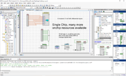
This is easily done in a single chip, PSOC 5LP, has internal muxes (digital and analog), SAR, OpAmps,
ARM core, USB, logic fabric, counter/timer/shift/LUTs/12 bit sar/20bit delsig.......


Done with low end part -


Something like this -

1630666227100.png


Regards, Dana.
 

Attachments

  • 1630669084372.png
    1630669084372.png
    223.7 KB · Views: 96
Last edited:

Hi,

you need to tell us the trigger requirements.

***
Generally you need:
* a clock divider (counter) down to 4800Hz sampling rate.
* you may use one of these counter bit outputs for SPI clock timing
* the 4800 Hz clock is the input for an address counter.
* I´d sample continously and save the data 0..9599
* on trigger event (save the actual address counter value) and go on for the next 4800 samples.
* then stop

Read out beginning from (saved addresscounter - 4800)

Klaus
 

Status
Not open for further replies.

Part and Inventory Search

Welcome to EDABoard.com

Sponsor

Back
Top