Continue to Site

Welcome to EDAboard.com

Welcome to our site! EDAboard.com is an international Electronics Discussion Forum focused on EDA software, circuits, schematics, books, theory, papers, asic, pld, 8051, DSP, Network, RF, Analog Design, PCB, Service Manuals... and a whole lot more! To participate you need to register. Registration is free. Click here to register now.

Arduino UNO and UltraSonic Sensor JSN-SR04T

Status
Not open for further replies.

imranahmed

Advanced Member level 3
Joined
Dec 4, 2011
Messages
817
Helped
3
Reputation
6
Reaction score
3
Trophy points
1,298
Location
Karachi,Pakistan
Activity points
6,492
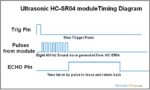
Please let me know I want to place UltraSonic Sensor JSN-SR04T far from Arduino UNO, 80 feet far from Arduino UNO from ground level to 3rd, 4th or 5th floor.

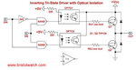
But I am stuck in sending Trigger and Echo data because it have +5V data voltage. How to increase data voltages to transmit far distance.

Any module available or any hint please let me know.

Thanks.
 

Hi,

almost 25 meters is quite a long distance. How does your wire harness looks like e.g. wire diameter, shielding, twisted, ... ? Are you using a single 5 V power supply? If so, which supply voltage are you measuring at the other end (25 m) of your cable? Also, the cable might already represent a to high capacitance (e.g. a coaxial cable has about 100 pF/m), so due to charging and discharging of this capacitance the required high-level voltage might be never reached. Do you have access to a scope? If so, how does the signal/data waveform looks like?


I would not recommend the use of a single ended data transmission over such a long distance, as it is prone to EMI. A differential approch with sufficient current driving capability would be more reliable approach.

BR

Yes 25 meters long distance.
Wire is not decided yet.
Using 12V power supply then step down by 7805.
Not measuring yet because wire is not purchased.
Thinking for using 2-core shielded wire.
No, scope not used.
Waveform of ultra sonic sensor is mentioned in attachment.
 

Attachments

  • Ultrasonic_timing_diagram_HC-SR04.png
    Ultrasonic_timing_diagram_HC-SR04.png
    73.8 KB · Views: 120

Hi,

a solution would be to use NMOST transistors in combination with your 12 V supply to create an open drain communication, as it seems the pins are unidirectional. But by doing so you will need additional inverters, preferably with TTL compatible inputs and CMOS outputs.

With this approach the signal HIGH level along the wires will be 12 V. The inverters will translate this 12 V to 5 V.

But it is still a single ended communicatin.

BR
 

    imranahmed

    Points: 2
    Helpful Answer Positive Rating
Hi,

a solution would be to use NMOST transistors in combination with your 12 V supply to create an open drain communication, as it seems the pins are unidirectional. But by doing so you will need additional inverters, preferably with TTL compatible inputs and CMOS outputs.

With this approach the signal HIGH level along the wires will be 12 V. The inverters will translate this 12 V to 5 V.

But it is still a single ended communicatin.

BR

Thank you for helpful answers.

I can use 4 systems for 2-way communication.
For Ultrasonic sensor side 1 for trigger pin 5V to 12V then 1 for use inverter 12V to 5V and other is connected with
echo pin of ultrasonic sensor for 5V to 12V then last for Arduino pin 12V to 5V.

Is this good approach?
 

Hi,

TX -------> RX

Transmit (TX) signals drive the gate of a NMOST, drain is connected to a 12 V by a pull-up resistor.

Receive (RX) signals are converted by an inverter from 12 V to 5 V. The inverter should accept TTL input levels.

BR
 
Hi,

TX -------> RX

Transmit (TX) signals drive the gate of a NMOST, drain is connected to a 12 V by a pull-up resistor.

Receive (RX) signals are converted by an inverter from 12 V to 5 V. The inverter should accept TTL input levels.

BR
Awesome
I will try it.
 

OK tell us how it works.

I still would recommend a differential signal for such a long distance.

BR
 
OK tell us how it works.

I still would recommend a differential signal for such a long distance.

BR
I found from bristolwatch.com a circuit for logic level converter.
I think it is easy.
 

Attachments

  • Logic Level Converter from BristolWatch.jpg
    Logic Level Converter from BristolWatch.jpg
    30 KB · Views: 94

Hi,

yes, use a level shifter that's the easiest solution to create the high voltage signal.

You can also use an other level shifter to translate this signal from 12 V to 5 V. But watch out that the 12 V to 5 V translator has a large enough voltage input margin, by means of a wider HIGH level input range e.g. from 8.4 V up to 12 V. As it seems you are afraid of the voltage drop along the line. Choose a level shifter which can source a high current as well, to enable a fast charging of capacitances.

BTW, with inverter accepting TTL input levels I had an “older“ IC in mind which can be operated at higher voltages (and not the levels itself). Sry for missleading you.

BR
No problem I am very thankful to you for guiding right.
Yes I will do it with your instructions.
 

Sound waves normally do pass through liquids very well but they have a really had time going from one liquid to another. This is true of the air - water barrier as well. Sound waves generated on either side of the barrier tend to be reflected back into the fluid at the barrier. As a result, attempting to measure the top of a water surface from an air environment should work just fine.
 
Sound waves normally do pass through liquids very well but they have a really had time going from one liquid to another. This is true of the air - water barrier as well. Sound waves generated on either side of the barrier tend to be reflected back into the fluid at the barrier. As a result, attempting to measure the top of a water surface from an air environment should work just fine.
Yes exactly same thing I am developing.
Over-head tank empty or not by sensing water level.
Over-head tank places in top of the building but for greater than 2 floor needs to send signal for ultrasonic sensor.
 

Status
Not open for further replies.

Similar threads

Part and Inventory Search

Welcome to EDABoard.com

Sponsor

Back
Top