Continue to Site

Welcome to EDAboard.com

Welcome to our site! EDAboard.com is an international Electronics Discussion Forum focused on EDA software, circuits, schematics, books, theory, papers, asic, pld, 8051, DSP, Network, RF, Analog Design, PCB, Service Manuals... and a whole lot more! To participate you need to register. Registration is free. Click here to register now.

Arduino PID temperature control

Status
Not open for further replies.

beard_99

Newbie
Joined
Jul 31, 2020
Messages
4
Helped
0
Reputation
0
Reaction score
0
Trophy points
1
Activity points
24
Hello, I am relatively new to microcontrollers and to electronics in general. I need some help in building a PID temperature controller for a soldering iron, with K-type thermocouple sensor.
The code is not working, it only displays the temperature but the iron is not heating.
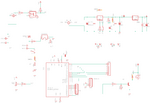
Please find attached the code and the schematic.

C:
//source: http://www.instructables.com/id/Arduino-controlled-light-dimmer-The-circuit/?lang=pt&ALLSTEPS
//Arduino controlled light dimmer: The software III
//The code below has been confirmed to work on the Leonardo

/*
  AC Light Control

  Updated by Robert Twomey

  Changed zero-crossing detection to look for RISING edge rather
  than falling.  (originally it was only chopping the negative half
  of the AC wave form).

  Also changed the dim_check() to turn on the Triac, leaving it on
  until the zero_cross_detect() turn's it off.

  Adapted from sketch by Ryan McLaughlin
  <a href="http://www.arduino.cc/cgi-bin/yabb2/YaBB.pl?num=1230333861/30" rel="nofollow"> <a rel="nofollow"> http://www.arduino.cc/cgi-bin/yabb2/YaBB.pl?num=1...</a>>
  (now here: <a rel="nofollow"> http://www.arduino.cc/cgi-bin/yabb2/YaBB.pl?num=1...</a>

*/

#include <TimerOne.h>          // Avaiable from <a href="http://www.arduino.cc/playground/Code/Timer1" rel="nofollow"> <a href="http://www.arduino.cc/playground/Code/Timer1" rel="nofollow"> http://www.arduino.cc/cgi-bin/yabb2/YaBB.pl?num=1...</a>
#include <PID_v1.h>
#include <max6675.h>
#include <LiquidCrystal.h>
#include <SPI.h>
#include <Wire.h>

#define thermoDO 12
#define thermoCS 10
#define thermoCLK 13
#define potentiometer A0
#define zerocrossing 2
#define relay A1

float realTemperature;
int pottemperature;

LiquidCrystal lcd(3, 4, 5, 6, 8, 9);

byte thermometer[8] = //icon for termometer
{
  B00100,
  B01010,
  B01010,
  B01110,
  B01110,
  B11111,
  B11111,
  B01110
};

byte arrow[8] = //icon for arrow
{
  B11000,
  B01100,
  B00110,
  B00011,
  B00011,
  B00110,
  B01100,
  B11000
};

MAX6675 thermocouple(thermoCLK, thermoCS, thermoDO);

double Setpoint, Input, Output;
double aggKp = 4, aggKi = 0.2, aggKd = 1;
double consKp = 1, consKi = 0.05, consKd = 0.25;
PID myPID(&Input, &Output, &Setpoint, consKp, consKi, consKd, DIRECT);

volatile int i = 0;             // Variable to use as a counter
volatile boolean zero_cross = 0; // Boolean to store a "switch" to tell us if we have crossed zero
int triac = 7;                // Output to Opto Triac
int dim = 0;                    // Dimming level (0-128)  0 = on, 128 = 0ff
int inc = 1;                    // counting up or down, 1=up, -1=down

int freqStep = 75;    // This is the delay-per-brightness step in microseconds.
// For 60 Hz it should be 65
// It is calculated based on the frequency of your voltage supply (50Hz or 60Hz)
// and the number of brightness steps you want.
//
// Realize that there are 2 zerocrossing per cycle. This means
// zero crossing happens at 120Hz for a 60Hz supply or 100Hz for a 50Hz supply.

// To calculate freqStep divide the length of one full half-wave of the power
// cycle (in microseconds) by the number of brightness steps.
//
// (120 Hz=8333uS) / 128 brightness steps = 65 uS / brightness step
// (100Hz=10000uS) / 128 steps = 75uS/step

void setup() {
  lcd.begin(16, 2);
  lcd.createChar(0, thermometer);
  lcd.createChar(1, arrow);
  lcd.setCursor(0, 0);
  lcd.print("STATIE DE LIPIT");
  myPID.SetMode(AUTOMATIC);
  myPID.SetOutputLimits(0, 128);
  pinMode(relay, OUTPUT);
  pinMode(potentiometer, INPUT);
  pinMode(zerocrossing, INPUT_PULLUP);
  pinMode(triac, OUTPUT); // Set the Triac pin as output
  delay(1200);
  lcd.clear();
  digitalWrite(triac, LOW);
  digitalWrite(relay, HIGH);
  attachInterrupt(digitalPinToInterrupt(2), zero_cross_detect, RISING);    // Attach an Interupt to Pin 2 (interupt 0) for Zero Cross Detection
  Timer1.initialize(freqStep);                      // Initialize TimerOne library for the freq we need
  Timer1.attachInterrupt(dim_check, freqStep);
  // Use the TimerOne Library to attach an interrupt
  // to the function we use to check to see if it is
  // the right time to fire the triac.  This function
  // will now run every freqStep in microseconds.
}

void zero_cross_detect() {
  zero_cross = true;               // set the boolean to true to tell our dimming function that a zero cross has occured
  i = 0;
  digitalWrite(triac, LOW);       // turn off TRIAC (and AC)
}

// Turn on the TRIAC at the appropriate time
void dim_check() {
  if (zero_cross == true) {
    if (i >= dim) {
      digitalWrite(triac, HIGH); // turn on light
      i = 0; // reset time step counter
      zero_cross = false; //reset zero cross detection
    }
    else {
      i++; // increment time step counter
    }
  }
}

void loop() {
  pottemperature = analogRead(potentiometer);
  pottemperature = map(pottemperature, 0, 1023, 150, 400); //pottemperature is volatile
  Setpoint = pottemperature;
  realTemperature = thermocouple.readCelsius();
  Input = int(0.779828 * realTemperature - 10.3427); // make temperature an integer 
  if (isnan(realTemperature) || Input >= 432){
    while(true){
      displayErrors();
    }
  } else {
    updateDisplay();
  }
  double gap = abs(Setpoint - Input); //distance away from setpoint
  if (gap < 10)
  { //we're close to setpoint, use conservative tuning parameters
    myPID.SetTunings(consKp, consKi, consKd);
  }
  else
  {
    //we're far from setpoint, use aggressive tuning parameters
    myPID.SetTunings(aggKp, aggKi, aggKd);
  }
  myPID.Compute();
  dim = Output;
  delay(300);
}

void updateDisplay() {
  pottemperature = analogRead(potentiometer);
  Setpoint = map(pottemperature, 0, 1023, 150, 400);
  lcd.clear();
  lcd.setCursor(0, 0);
  lcd.write((byte)0);
  lcd.setCursor(2, 0);
  lcd.print((int)Setpoint);
  lcd.setCursor(6, 0);
  lcd.print((char)223); //degree sign
  lcd.setCursor(7, 0);
  lcd.print("C");
  lcd.setCursor(0, 1);
  lcd.write((byte)1);
  if (Input <= 45) {
    lcd.setCursor(2, 1);
    lcd.print("Lo");
  } else {
    lcd.setCursor(2, 1);
    lcd.print((int)Input);
  }
  lcd.setCursor(6, 1);
  lcd.print("[");
  lcd.setCursor(7, 1);
  lcd.print((int)realTemperature);
  lcd.setCursor(10, 1);
  lcd.print("]");
  lcd.setCursor(12, 1);
  lcd.print((char)223);
  lcd.setCursor(13, 1);
  lcd.print("C");
}

void displayErrors() {
  digitalWrite(relay, LOW);
  lcd.clear();
  lcd.setCursor(0, 0);
  lcd.write((byte)0);
  lcd.setCursor(1, 0);
  lcd.write((byte)0);
  lcd.setCursor(5, 0);
  lcd.print("ERROR!");
  lcd.setCursor(14, 0);
  lcd.write((byte)0);
  lcd.setCursor(15, 0);
  lcd.write((byte)0);
}
 

Attachments

  • schematic_ss.png
    schematic_ss.png
    33 KB · Views: 254

I’m not about to debug ALL your code, but I have a few questions.

It looks like led1 is only on when the iron is off, is that really what you want?

There’s no output in your code named “out” which is the signal that drives your opto.

have you looked at your output with a scope?
 

1. LED1 will be on only when the soldering iron will be off. This is something like a "error led".
2. I modified the code as shown below, it works now, I am not 100% it is correct, please have a look if you can.
3. Yes, please find attached the following screenshots from the scope: DS0146 and DS0147 - on the heater, at some different moments of time, DS0134 and DS0138 - yellow=zero crossing signal (pin 2), blue=output from Arduino Nano (pin 7).

C:
#include <TimerOne.h>     
#include <PID_v1.h>
#include <max6675.h>
#include <LiquidCrystal.h>
#include <SPI.h>
#include <Wire.h>

#define thermoDO 12
#define thermoCS 10
#define thermoCLK 13
#define potentiometer A0
#define zerocrossing 2
#define relay A1

float realTemperature;
int pottemperature;

LiquidCrystal lcd(3, 4, 5, 6, 8, 9);

byte thermometer[8] = //icon for termometer
{
  B00100,
  B01010,
  B01010,
  B01110,
  B01110,
  B11111,
  B11111,
  B01110
};

byte arrow[8] = //icon for arrow
{
  B11000,
  B01100,
  B00110,
  B00011,
  B00011,
  B00110,
  B01100,
  B11000
};

MAX6675 thermocouple(thermoCLK, thermoCS, thermoDO);
//
double Setpoint, Input, Output;
double aggKp = 4, aggKi = 0.2, aggKd = 1;
double consKp = 1, consKi = 0.05, consKd = 0.25;
PID myPID(&Input, &Output, &Setpoint, consKp, consKi, consKd, DIRECT);

volatile int i = 0;             // Variable to use as a counter
volatile boolean zero_cross = 0; // Boolean to store a "switch" to tell us if we have crossed zero
int triac = 7;                // Output to Opto Triac
int dim = 0;                    // Dimming level (0-128)  0 = on, 128 = 0ff
int inc = 1;                    // counting up or down, 1=up, -1=down

int freqStep = 75;    // This is the delay-per-brightness step in microseconds.
// (100Hz=10000uS) / 128 steps = 75uS/step

void setup() {
  lcd.begin(16, 2);
  lcd.createChar(0, thermometer);
  lcd.createChar(1, arrow);
  lcd.setCursor(0, 0);
  lcd.print("STATIE DE LIPIT");
  myPID.SetMode(AUTOMATIC);
  myPID.SetOutputLimits(0, 128);
  pinMode(relay, OUTPUT);
  pinMode(potentiometer, INPUT);
  pinMode(zerocrossing, INPUT_PULLUP);
  pinMode(triac, OUTPUT); // Set the Triac pin as output
  delay(1200);
  lcd.clear();
  digitalWrite(relay, HIGH);
  attachInterrupt(digitalPinToInterrupt(2), zero_cross_detect, RISING);    // Attach an Interupt to Pin 2 (interupt 0) for Zero Cross Detection
  Timer1.initialize(freqStep);                      // Initialize TimerOne library for the freq we need
  Timer1.attachInterrupt(dim_check, freqStep);
}

void zero_cross_detect() {
  zero_cross = true;               // set the boolean to true to tell our dimming function that a zero cross has occured
  i = 0;
  digitalWrite(triac, LOW);       // turn off TRIAC (and AC)
}

// Turn on the TRIAC at the appropriate time
void dim_check() {
  if (zero_cross == true) {
    if (i >= dim) {
      digitalWrite(triac, HIGH); // turn on light
      i = 0; // reset time step counter
      zero_cross = false; //reset zero cross detection
    }
    else {
      i++; // increment time step counter
    }
  }
}

void loop() {
  pottemperature = analogRead(potentiometer);
  Setpoint = map(pottemperature, 0, 1023, 150, 400); //pottemperature is volatile
  realTemperature = thermocouple.readCelsius();
  Input = int(0.779828 * realTemperature - 10.3427); // make temperature an integer
  if (isnan(realTemperature) || Input >= 432) {
    while (true) {
      displayErrors();
    }
  } else {
    updateDisplay();
  }
  double gap = abs(Setpoint - Input); //distance away from setpoint
  if (gap < 10)
  { //we're close to setpoint, use conservative tuning parameters
    myPID.SetTunings(consKp, consKi, consKd);
  }
  else
  {
    //we're far from setpoint, use aggressive tuning parameters
    myPID.SetTunings(aggKp, aggKi, aggKd);
  }
  myPID.Compute();
  dim = map(Output, 0, 128, 128, 0);
  delay(300);
}

void updateDisplay() {
  lcd.clear();
  lcd.setCursor(0, 0);
  lcd.write((byte)0);
  lcd.setCursor(2, 0);
  lcd.print((int)Setpoint);
  lcd.setCursor(6, 0);
  lcd.print((char)223); //degree sign
  lcd.setCursor(7, 0);
  lcd.print("C");
  lcd.setCursor(0, 1);
  lcd.write((byte)1);
  if (Input <= 45) {
    lcd.setCursor(2, 1);
    lcd.print("Lo");
  } else {
    lcd.setCursor(2, 1);
    lcd.print((int)Input);
  }
  lcd.setCursor(6, 1);
  lcd.print("[");
  lcd.setCursor(7, 1);
  lcd.print((int)realTemperature);
  lcd.setCursor(10, 1);
  lcd.print("]");
  lcd.setCursor(12, 1);
  lcd.print((char)223);
  lcd.setCursor(13, 1);
  lcd.print("C");
}

void displayErrors() {
  digitalWrite(relay, LOW);
  lcd.clear();
  lcd.setCursor(0, 0);
  lcd.write((byte)0);
  lcd.setCursor(1, 0);
  lcd.write((byte)0);
  lcd.setCursor(5, 0);
  lcd.print("ERROR!");
  lcd.setCursor(14, 0);
  lcd.write((byte)0);
  lcd.setCursor(15, 0);
  lcd.write((byte)0);
  delay(300);
}
 

Attachments

  • DS0146.jpg
    DS0146.jpg
    34.1 KB · Views: 89
  • DS0147.jpg
    DS0147.jpg
    35.8 KB · Views: 92
  • DS0134.jpg
    DS0134.jpg
    39.2 KB · Views: 98
  • DS0138.jpg
    DS0138.jpg
    39.9 KB · Views: 175

Please find new code below:
C:
#include <TimerOne.h>       
#include <PID_v1.h>
#include <max6675.h>
#include <LiquidCrystal.h>
#include <SPI.h>
#include <Wire.h>

#define thermoDO 12
#define thermoCS 10
#define thermoCLK 13
#define potentiometer A0
#define zerocrossing 2
#define relay A1

float realTemperature;
int pottemperature;

#define test_pin A2

LiquidCrystal lcd(3, 4, 5, 6, 8, 9);

byte thermometer[8] = //icon for termometer
{
  B00100,
  B01010,
  B01010,
  B01110,
  B01110,
  B11111,
  B11111,
  B01110
};

byte arrow[8] = //icon for arrow
{
  B11000,
  B01100,
  B00110,
  B00011,
  B00011,
  B00110,
  B01100,
  B11000
};

MAX6675 thermocouple(thermoCLK, thermoCS, thermoDO);

double Setpoint, Input, Output;
double aggKp = 4, aggKi = 0.2, aggKd = 1;
double consKp = 1, consKi = 0.05, consKd = 0.25;
PID myPID(&Input, &Output, &Setpoint, consKp, consKi, consKd, DIRECT);

int period = 500;
unsigned long time_now = 0;

volatile int i = 0;             // Variable to use as a counter
volatile boolean zero_cross = 0; // Boolean to store a "switch" to tell us if we have crossed zero
int triac = 7;                // Output to Opto Triac
int dim = 0;                    // Dimming level (0-128)  0 = on, 128 = 0ff
int inc = 1;                    // counting up or down, 1=up, -1=down

int freqStep = 75;    // This is the delay-per-brightness step in microseconds
// (100Hz=10000uS) / 128 steps = 75uS/step

void setup() {
  pinMode(test_pin, OUTPUT);
  digitalWrite(test_pin, LOW);
  lcd.begin(16, 2);
  lcd.createChar(0, thermometer);
  lcd.createChar(1, arrow);
  lcd.setCursor(0, 0);
  lcd.print("STATIE DE LIPIT");
  myPID.SetMode(AUTOMATIC);
  myPID.SetOutputLimits(0, 128);
  pinMode(relay, OUTPUT);
  pinMode(potentiometer, INPUT);
  pinMode(zerocrossing, INPUT_PULLUP);
  pinMode(triac, OUTPUT); // Set the Triac pin as output
  delay(1200);
  lcd.clear();
  digitalWrite(relay, HIGH);
  attachInterrupt(digitalPinToInterrupt(2), zero_cross_detect, RISING);    // Attach an Interupt to Pin 2 (interupt 0) for Zero Cross Detection
  Timer1.initialize(freqStep);                      // Initialize TimerOne library for the freq we need
  Timer1.attachInterrupt(dim_check, freqStep);
}

void zero_cross_detect() {
  zero_cross = true;               // set the boolean to true to tell our dimming function that a zero cross has occured
  i = 0;
  digitalWrite(triac, LOW);       // turn off TRIAC (and AC)
}

// Turn on the TRIAC at the appropriate time
void dim_check() {
  if (zero_cross == true) {
    if (i >= dim) {
      digitalWrite(triac, HIGH); // turn on light
      i = 0; // reset time step counter
      zero_cross = false; //reset zero cross detection
    }
    else {
      i++; // increment time step counter
    }
  }
}

void loop() {
  if ((unsigned long)(millis() - time_now) > period) {
    digitalWrite(test_pin, HIGH);
    time_now = millis();
    pottemperature = analogRead(potentiometer);
    Setpoint = map(pottemperature, 0, 1023, 150, 400); //pottemperature is volatile
    realTemperature = thermocouple.readCelsius();
    Input = int(0.779828 * realTemperature - 10.3427); // make temperature an integer
    if (isnan(realTemperature) || Input >= 432) {
      while (true) {
        displayErrors();
      }
    } else {
      updateDisplay();
    }
    double gap = abs(Setpoint - Input); //distance away from setpoint
    if (gap < 10)
    { //we're close to setpoint, use conservative tuning parameters
      myPID.SetTunings(consKp, consKi, consKd);
    }
    else
    {
      //we're far from setpoint, use aggressive tuning parameters
      myPID.SetTunings(aggKp, aggKi, aggKd);
    }
    myPID.Compute();
    dim = map(Output, 0, 128, 128, 0);
    digitalWrite(test_pin, LOW);
  }
}

void updateDisplay() {
  lcd.clear();
  lcd.setCursor(0, 0);
  lcd.write((byte)0);
  lcd.setCursor(2, 0);
  lcd.print((int)Setpoint);
  lcd.setCursor(6, 0);
  lcd.print((char)223); //degree sign
  lcd.setCursor(7, 0);
  lcd.print("C");
  lcd.setCursor(0, 1);
  lcd.write((byte)1);
  if (Input <= 45) {
    lcd.setCursor(2, 1);
    lcd.print("Lo");
  } else {
    lcd.setCursor(2, 1);
    lcd.print((int)Input);
  }
  lcd.setCursor(6, 1);
  lcd.print("[");
  lcd.setCursor(7, 1);
  lcd.print((int)realTemperature);
  lcd.setCursor(10, 1);
  lcd.print("]");
  lcd.setCursor(12, 1);
  lcd.print((char)223);
  lcd.setCursor(13, 1);
  lcd.print("C");
}

void displayErrors() {
  digitalWrite(relay, LOW);
  lcd.clear();
  lcd.setCursor(0, 0);
  lcd.write((byte)0);
  lcd.setCursor(1, 0);
  lcd.write((byte)0);
  lcd.setCursor(5, 0);
  lcd.print("ERROR!");
  lcd.setCursor(14, 0);
  lcd.write((byte)0);
  lcd.setCursor(15, 0);
  lcd.write((byte)0);
  delay(500);
}

Please also find attached screenshots from oscilloscope (in the first image: yellow - pin 2 waveform, blue - output pin 7 waveform and in the last 3 images: the chopped sine wave on the heater).
DS0174.jpgDS0182.jpgDS0183.jpgDS0191.jpg

Please have a look and tell me what you think ?
 

It looks like it’s doing phase control. whether your code is right, I can’t say. Is your soldering iron maintain temperature? If so, then it’s working.
 

Yes it is doing phase control.
Regarding the temperature, I made a quick test, by melting 60/40 solder on a piece of 55x30mm PCB at 320 C, and it maintained the temperature.
 

Status
Not open for further replies.

Similar threads

Part and Inventory Search

Welcome to EDABoard.com

Sponsor

Back
Top