boylesg
Advanced Member level 4
- Joined
- Jul 15, 2012
- Messages
- 1,023
- Helped
- 5
- Reputation
- 10
- Reaction score
- 6
- Trophy points
- 1,318
- Location
- Epping, Victoria, Australia
- Activity points
- 11,697
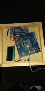
The right image is of my full setup.
The solenoids switch 24AC through standard solenoid valves from Bunnings Australia.
The LCD screen just allows you to see what is going on inside the software as it boots up and operates.
The blue PCB is custom one I designed and includes a slot for a bluetooth modem, and bridge rectifier and a DC to DC converter to provide the 5V for the digital electronics.
The left image is just a mega with an data logger shield and a ESP13 shield - just to show the essential hardware without the custom PCB in the way.


This system works flawlessly at my house and in 3 medical clinics.
But as soon as I take to one particular house I am getting hardware failures.
The SD card read can't 'mount' the SD card and read from it.
The firmware on the ESP13 shield may get wiped or damaged and I have to reload it.
The system just does not work.
And this is after two completely separate system with no re-used hardware.
My suspicion is that there are power spikes or something coming through the power in the house or may be external to the house.
I learned early on in the development of this that power spikes are deadly to digital electronics - i.e. inductive kick back from the solenoids was resetting the meg ever time.
Until Brian I think it was pointed out a device (whose designation I forget off hand) that snuffs kick back spikes.
As soon as I installed one of these close to where the solenoid valves are wired to my custom PCB, this problem disappeared.
So with this other less tangible problem, I can come to no other conclusion that there are small power spikes coming into my electronics from the outside.
May be a faulty appliance else where in the house?
All I can try is to add some sort of protection against spikes that might be leaking through the bridge rectifier and DC to DC converter.
However I have no idea where to begin.
Any suggestions please?
The solenoids switch 24AC through standard solenoid valves from Bunnings Australia.
The LCD screen just allows you to see what is going on inside the software as it boots up and operates.
The blue PCB is custom one I designed and includes a slot for a bluetooth modem, and bridge rectifier and a DC to DC converter to provide the 5V for the digital electronics.
The left image is just a mega with an data logger shield and a ESP13 shield - just to show the essential hardware without the custom PCB in the way.
This system works flawlessly at my house and in 3 medical clinics.
But as soon as I take to one particular house I am getting hardware failures.
The SD card read can't 'mount' the SD card and read from it.
The firmware on the ESP13 shield may get wiped or damaged and I have to reload it.
The system just does not work.
And this is after two completely separate system with no re-used hardware.
My suspicion is that there are power spikes or something coming through the power in the house or may be external to the house.
I learned early on in the development of this that power spikes are deadly to digital electronics - i.e. inductive kick back from the solenoids was resetting the meg ever time.
Until Brian I think it was pointed out a device (whose designation I forget off hand) that snuffs kick back spikes.
As soon as I installed one of these close to where the solenoid valves are wired to my custom PCB, this problem disappeared.
So with this other less tangible problem, I can come to no other conclusion that there are small power spikes coming into my electronics from the outside.
May be a faulty appliance else where in the house?
All I can try is to add some sort of protection against spikes that might be leaking through the bridge rectifier and DC to DC converter.
However I have no idea where to begin.
Any suggestions please?