Continue to Site

Welcome to EDAboard.com

Welcome to our site! EDAboard.com is an international Electronics Discussion Forum focused on EDA software, circuits, schematics, books, theory, papers, asic, pld, 8051, DSP, Network, RF, Analog Design, PCB, Service Manuals... and a whole lot more! To participate you need to register. Registration is free. Click here to register now.

APR9600 voice recorder problem

Status
Not open for further replies.

Akhil Mohan

Member level 2
Joined
May 13, 2011
Messages
53
Helped
2
Reputation
4
Reaction score
2
Trophy points
1,288
Activity points
1,731
Hello,

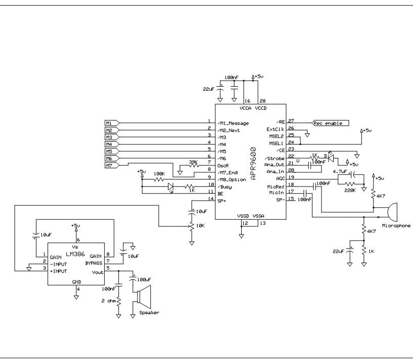
I am using APR9600 voice recorder IC in my project and have some doubts regarding the busy pin mentioned in the datasheet. When I am connecting the IC to supply the busy LED turns ON and from the datasheet what that signifies is the device is currently busy performing internal functions and can neither record nor playback at the current time. Why this happens in my case? I am not able to record the sound file (.wav) from PC.
(The strobe LED is also blinking continuously when connected to the supply.)

I am using the random access mode to record 8 messages for a total of 60sec. I am using a stereo jack and connected to ANA IN by means of 1K and 0.1uf and there is a connection between ANA in and out by a 0.1uf cap.
View attachment APR9600.pdf

Thanks in Advance,
Akhil
 
Last edited:

Hello,

well. u should enable beep. BE .
so that u can know the start and stop of recording.
when u press me for recording message 1 in recording mode you will hear starting beep sound.
and u should press m1 for message 1 until recording compelled.
after compliting recording u will hear stop beep sound.

for recording mode pin27 in pdip package should be low (ground)
pin 11 sholud be high to enable BE.
 
I have done that already, but not hearing any beep sound when there is a high to low transition on pin1. What will be the voltege at SP+on power on, currently it is zero for me and am using TIP122 instead of ST 8050 NPN transistor
 
Last edited:

after hearing beep sound you are required to record your voice and press stop button did you check your circuit ?

---------- Post added at 13:35 ---------- Previous post was at 13:34 ----------

i can give you another circuit but you have to wait for two days i am outside my workstation is it ok for you
 
I have checked the circuit, Can you explain how the strobe pin and SP+ works or the values on power up?
Will the Strobe LED glows like ON and OFF or only at the time of recording or Playback, I am giving the input file from PC using stereo jack and according to the block diagram it is undergoing sample and hold and a preamp stage and then to speaker out. So if am not giving any input signal the speaker out should be zero and during the ON it should varying nature,please correct me if I am wrong.

@Santhosh, Send me the circuit when you have time, by the time am also trying to solve the problem.

Thanks in advance,
Akhil
 

[QUOTE=Akhil Mohan;923895
don't use meter to see the signal at sp+ pin. connect the speaker as describe in datasheet.

first u confirm the your circuit diagram as data sheet.
connect pin 20 and pin 21 through 0.1 micro farad capacitor as shown in diagram.it is compulsory.
if it not work let me know.
and send me your exact circuit diagram . and then i will tell you what to do.

i have done lots of project of this ic. and i am recording the sound only from my laptop's sound card. i am not using microphone.
it must work.
 

Hi guys,
I have tried the circuit diagram given in the datasheet (see my first post) in random access mode using 8 switches. I have used internal oscillator with a resistor equal to 84K and made BE=1. Then set the initial conditions for CE and RE as low for record. I have also included the feedback between ANA in and out by 0.1uf then connections to stereo jack as mentioned in the datasheet. Then I have connected a speaker (internal R=8ohm) as mentioned in the datasheet,(TIP122 in place of 8050).
When am giving 5V supply the strobe LED and Busy LED glows for few seconds and then goes OFF. I think that means my IC is working properly. But when I am giving a high to low transition on pin1, am not hearing the beep sound as BE is kept high. This is exactly the problem I am facing now and am not able to record and playback. What is wrong in the circuit (Please see datasheet) and how it can be rectified?

Waiting for a good reply :)
Akhil
 

**broken link removed**
this is original datasheet.
kindly refer this. there is not any transistor.
place speaker directly between pin 14 and 15
and put pull up resistor array of 10k from m1 to m8. ( it is not shown in diagram but its useful for better design)
and check polarity of out put of audio signal which are comming out from your pc's sound card.
random access mode.jpg
record n play-17.jpg

i have attached diagram which shows connection for line in type recording.
and remove all component from pin 17 and 18 which are mic input connection.


and press down M1 continually for recording first message until recording stops.
and likewise press down M2 continually for recording second message until recording stops.

while playing, press M1 only once for playing . if u press M1 continually, then message will play continually.
 
dear sir, there is not any stop button in 8 message random access mode ..
after hearing beep sound you are required to record your voice and press stop button did you check your circuit ?

---------- Post added at 13:35 ---------- Previous post was at 13:34 ----------

i can give you another circuit but you have to wait for two days i am outside my workstation is it ok for you
 

But I have a speaker with internal resistance 8ohm and in the datasheet it is specified as 16ohm, is it k here?
The ANA input part is the same that I have connected. I will try the pull up resistor part that you have specified ,but why it is needed and why M8is connected to Supply by 100k.If I am using 8lines it acts as input line and then why that connection is done? some contradictory things specified in the datasheet!!
 

as you can see M8 pin has 100k pull up resistor.
but i suggest you to put the pull up resistor of 10 k at each pin from M1 to M8. and don't use 100 K pull Up at pin M8.
this is actual ic design mistake. in older datasheet it is not described 100k pull up at m8.
and 8 ohm will also do. but don't use lower than 8 ohm.

finally, clear all the doubts , now i think this will solve your problem..
if this doesn't work, then check proper soldering of each connection. and after that you should try to check after replacing ic.
 

Will try and let you know de results :)
Thanks so much for the advice
 

you are welcome..
let me know ,,,, if is it work or not...?
i am new to this site. i joined this site today only...


Dont make a request to others to click on the helpful button... leave it to user..

ok sir..
 
Last edited:

this works for me everytime i rig this up...


Hello,
@CK Shivram, I have few changes in the above circuit which are I have included pull up resistors of 10K from M1to M6 and that voltage levela are k. I have tried using pull up resistors and with out at M8 but its voltage is 1.36 and the min for ON is 2V. What can be the reason? I have connected the M9 pin to GND via a switch and also a connection to Vcc through 10K from M9 pin is done, its voltage level is 2.4V and I think that is k.

When I am giving 5V power to the IC the busy LED glows and some times the strobe LED blinks. Also a noise like sound is coming through out from the speaker, Why this happens ans how to rectify that thing?

In the LM386 connection I do not have a 10K pot, and now using a 100K one, But what my doubt is the IC has an internal amplifier, so why we need an audio amplifier in the SP+ out. The diaphragm movement is not good due to some dc components (100uf is there, still !!!), Is the LM 386 stage makes the system complex, I am not able to understand how this IC works ie How does SP+ and SP- produces an amplified output based on input ie sample and hold and LPF one.

Is am making my point in a confusing manner, any way I am sorry If I am doing that :)
 

Instead of a stero jack i prefer you to use a small mic available in the market.... i forgot its name but its small round type.... stereo jacks cause some impedance problem as per my observation..... and use a small speaker <8 ohms speaker....
 

But it will come in to play when I am recording something, but my problem is on power up some noisy sounds are coming, and Busy LED is ON. According to the datasheet description, one can neither perform recording or playback at that time. And any idea why these kinds voltage levels coming in M8 and M9 pins as I mentioned that thing my previous post :)
 

Hello,
I have connected the M9 pin to GND via a switch and also a connection to Vcc through 10K from M9 pin is done, its voltage level is 2.4V and I think that is k.
there is not any M9 Pin..
don't make it confusing...

no need of amplification for small speaker.
you can connect speaker directly to SP+ and SP-.
and put pull up of 10 kilo-ohm resistor from M1 to M8 all pin.( pin1, pin2....... pin6. and pin 8, pin9).
i think you have some misunderstanding.
kindly give us you exact circuit diagram so that we can clarify.
 

Status
Not open for further replies.

Similar threads

Part and Inventory Search

Welcome to EDABoard.com

Sponsor

Back
Top