Continue to Site

Welcome to EDAboard.com

Welcome to our site! EDAboard.com is an international Electronics Discussion Forum focused on EDA software, circuits, schematics, books, theory, papers, asic, pld, 8051, DSP, Network, RF, Analog Design, PCB, Service Manuals... and a whole lot more! To participate you need to register. Registration is free. Click here to register now.

Antenna Pattern Measurement

Status
Not open for further replies.

Julew

Member level 1
Joined
Apr 7, 2011
Messages
40
Helped
1
Reputation
2
Reaction score
1
Trophy points
1,288
Activity points
1,586
Hello,

I am measuring a 2.4Ghz Zigbee device´s radiation pattern. I haven´t got an anechoic chamber so i am measuring it in "free space" using a tripod. One side i have the device transmiting at 0dBm in a rotary head. In the other side i have a 5 segment Yagi antenna (cheap, high gain and polarized) connected to a spectrum analyzer. I would like your opinion about tripod position. They are 1.2 meter from graound and 3 meters away as you can see in the picture.
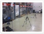
Situación Medida foto.jpg
Situación Medida.jpg

I know that i am going to have reflections. I think walls are not going to affect to much the measurement. I am receiving -50dBm signal so wall signals must be -100dBm. I have been moving the setup and the measured pattern is more or less equal. Maybe the ground has more effect in the measurement but i don´t know how to avoid it. How would you improve the measurement setup?

Thanks a lot!
 

The best (and easiest) improvement for your setup is to go outside of the chamber, in an open field.
If the height of the test antennas is greater than about 10λ (>1.3m in your case) the ground reflections will be very low.
 

vfone: The best (and easiest) improvement for your setup is to go outside of the chamber, in an open field.
Yes vfone. This is the next step but the infrastructure is not easy and the weather here in Basque Country is crazy!


vfone: If the height of the test antennas is greater than about 10λ (>1.3m in your case) the ground reflections will be very low.

Why 10λ??
 

You can not take good pattern measurements because:
1) there are too many reflections from those metal objects in the room
2) the yagi antenna is physically too big for the short distance between the two antennas, so you do not really know "where" it is.

I would go with a much smaller antenna in place of the yagi. A directional one would make sense as it will tend to somewhat reduce multipath reception. A single patch antenna might be a good choice.

You can try to drape microwave absorbing sheet from the ceiling to minizmize reflections, without building an actual anechoic chamber.

Electromagnetic Field Shielding Fabrics
 
Last edited:
  • Like
Reactions: Julew

    Julew

    Points: 2
    Helpful Answer Positive Rating
biff:
2) the yagi antenna is physically too big for the short distance between the two antennas, so you do not really know "where" it is.

I dont understand this. In Antenas book (ISN:84-8301-625-7) mention that there are 3 limitations:

R > 10 λ
R > 10 D
R > 2 D²/ λ

R=Distance from AUT
D=AUT size

In my setup i respect this limitations.


This web is super freak men! Anyway, it is very interesting but the fabrics are quite expensive. Thanks yo a lot!
 

Hello Biff44,

I dont know all the answers. I don´t understand you when you say that yagi antenna is too big. I newbie in RF and in my new company nobody have experience in RF. I just want to confirm that my setup is correct with people that has experience and improve it for the future. Thanks.
 

It is a lot of problem in your setup but it all depends on what you want to know and how big measurement errors that can be tolerated. Avoid metallic tripod, build something from the wooden pallets you have. Better if possible to measure with a VNA with time discriminator as all reflections are delayed compared to main signal.
Go outside! It is better and weather is not a problem. I do similar outside measurement even if it is raining or snowing with winds up to 30 m/s and -20 degree. Protect your equipment with clear plastic bags or something, avoid moisture in RF contacts. In case of thunderstorms, avoid measurements during flashes.
If you want to continue with an spectrum analyzer, build a transmitter connected to a simple dipole, via 1-2 meter coaxial cable ended with a resistor attenuator, as a reference unit. Dipole pattern is simple to verify and your system dynamic can also be verified by checking how deep your nulls are and that they are in correct place when you rotate the dipol. Use sleeves and a lot of ferrite tubes around all coaxial cables. Plenty. Check sleeve dipole at this link **broken link removed**. It is a simple antenna to build, efficiency near 100% and its expected radiation pattern is well known.
Resistor attenuator must be built by SMD resistor in a screened box. Reason for attenuator is that you then know that your system impedance is under some control without being able to measure that and then avoids unwanted ground current.
Check fig4 at this link for a typical setup Antenna Factors and Antenna Calibration.
If this is more then you is prepared to do, build at least a dipole and connect it to your DUT, it is done in 5 minutes. You only need some iron-wires and a coax cable. Also the copper-tube can be replaced by a few wires.
Whit this setup, check your max min radiation angels and signal levels in current environment. It is very likely that you then want to be outside and do your remaining measurements.
 
  • Like
Reactions: Julew

    Julew

    Points: 2
    Helpful Answer Positive Rating
Hi
I've studied replies of my roomattes.all af them correct and I think fo a proper and accurate mesurment you should consider them completly.but if you are forced to do in your manner I suggest you use some antenna that have clear parameters.for example the pattern is completly and accurately clear(you can find some standard antennas).then measure the pattern using your setup and find the difference between your mesurment and what reported in standard condition.then you can have some kind of calibration for your mesurment
 
  • Like
Reactions: Julew

    Julew

    Points: 2
    Helpful Answer Positive Rating
It is a lot of problem in your setup but it all depends on what you want to know and how big measurement errors that can be tolerated. Avoid metallic tripod, build something from the wooden pallets you have. Better if possible to measure with a VNA with time discriminator as all reflections are delayed compared to main signal.
Go outside! It is better and weather is not a problem. I do similar outside measurement even if it is raining or snowing with winds up to 30 m/s and -20 degree. Protect your equipment with clear plastic bags or something, avoid moisture in RF contacts. In case of thunderstorms, avoid measurements during flashes.
If you want to continue with an spectrum analyzer, build a transmitter connected to a simple dipole, via 1-2 meter coaxial cable ended with a resistor attenuator, as a reference unit. Dipole pattern is simple to verify and your system dynamic can also be verified by checking how deep your nulls are and that they are in correct place when you rotate the dipol. Use sleeves and a lot of ferrite tubes around all coaxial cables. Plenty. Check sleeve dipole at this link **broken link removed**. It is a simple antenna to build, efficiency near 100% and its expected radiation pattern is well known.
Resistor attenuator must be built by SMD resistor in a screened box. Reason for attenuator is that you then know that your system impedance is under some control without being able to measure that and then avoids unwanted ground current.
Check fig4 at this link for a typical setup Antenna Factors and Antenna Calibration.
If this is more then you is prepared to do, build at least a dipole and connect it to your DUT, it is done in 5 minutes. You only need some iron-wires and a coax cable. Also the copper-tube can be replaced by a few wires.
Whit this setup, check your max min radiation angels and signal levels in current environment. It is very likely that you then want to be outside and do your remaining measurements.

Kafeman: Thanks for your responce. It seems that Swedish people is stronger than Basque. :grin: I have to say that i have been living in Göteborg 8 months and i am alive. :wink:

Can i use a 2.4Ghz Wifi antenna as calibrator? I think that they are dipole antennas.

I don´t understand the function of the attenuators. In my case one side i have a device instead of an antenna and the output power is 0dBm but i can control de output power. I have a external SMA 20dB attenuator to install between Yagi and Spectrum Analyzer. Is this enough?

I am going to make the measurements in companys car parking and i am going to measure the dipole antenna to check if the setup is correct.
 

I recommend strongly that you build your own dipole, including some length of coaxial cable with a sleeve and ferrite. Cable is needed for several reasons but main thing is that your TX PCB will disturb dipole pattern if it placed to near your antenna.
Even a perfect designed dipole is not pure resistive 50 Ohm and when connected to a 50 Ohm coaxial cable will ground currents occur as result of impedance mismatch. If you have a VNA can you correct this to a certain degree but without that tool you do not know much about if it is the coax or the antenna that radiates.
A simple way is then to use 50 Ohm resistive attenuators, maybe 6 dB, as they attenuates any impedance mismatch and can if well built comes real close to 50 Ohm, without need to measure this. There are other reasons too, why you use these attenuators but less important now.
A 20 dB attenuator can be used for your TX but it will kill most of the signal and then reduce possible dynamic range.
I do always measurement below 400 MHz outside in free field. It is easy to believe that rainy weather disturbs your measurement but it is not a big problem as long as you can keep vital parts dry. Cold weather is harder as my fingers becomes stiff so it becomes harder to handle small things.
A nice thing with Goteborg is that it seldom becomes real cold but I prefer Basque if I have a choice.
 

Status
Not open for further replies.

Part and Inventory Search

Welcome to EDABoard.com

Sponsor

Back
Top