Continue to Site

Welcome to EDAboard.com

Welcome to our site! EDAboard.com is an international Electronics Discussion Forum focused on EDA software, circuits, schematics, books, theory, papers, asic, pld, 8051, DSP, Network, RF, Analog Design, PCB, Service Manuals... and a whole lot more! To participate you need to register. Registration is free. Click here to register now.

antenna array pattern with feeding network shows weird radiation pattern

lkminz

Member level 4
Joined
Jun 14, 2008
Messages
76
Helped
11
Reputation
22
Reaction score
10
Trophy points
1,288
Activity points
1,990
Hi all,

I am working to optimise antenna array of 12x8 element.
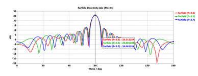
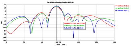
I came across a strange situation. My antenna array without Feeding network shows good broadside direction pattern.
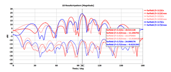
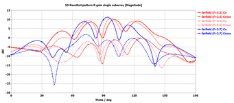
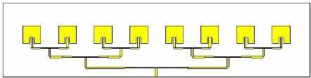
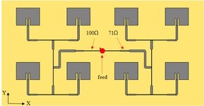
however, with addition of feeding network the radiation pattern shows high sidelobe and pattern shape distort a lot.

It would be great if someone can help me to understand the issue. Thank you.

I have attached with feeding network and without feeding network image below.
 

Attachments

  • with feeding network.png
    with feeding network.png
    97.9 KB · Views: 73
  • without feeding network.png
    without feeding network.png
    36.9 KB · Views: 72
Perhaps, this is the biggest problem in multi-antenna array design.
When start design a multi-antenna array, the first step solving/avoiding this issue is to chose the proper feed network for a particular array design. After the feed network type was chosen and designed, not much can be done from this side, to eliminate its influence on the array radiated pattern.
Other two factors, which combined to the feed network charatcteristic, and may affect the radiated pattern, are: the mutual coupling between antenna elements, and also the impedance change sensitivity of each element to its place into the array. Those two charateristics may be minimized by careful single-antenna element proper design.
Unfortunately, there is not a simple solution for this issue...
Thank you for the response.
As you said once the feed network is designed not much can be done there. I got 2 array antenna, one is single patch and another is stack patch. The feeding network seems to work well for single patch antenna but make the radiation pattern of stack patch antenna looks like there is uneven amplitude and phase shift for different element.
I checked the feeding network performance and use the feeding network endpoint phase and amplitude as a direct feed to antenna. with the direct amplitude and phase excitation the antenna array pattern is much better compared to array pattern with feeding network.
for this analysis I used 1x6 array. the result are attached below.

kindly see if you can suggest some points for improvement in radiaition pattern result.

Thanks.
 

Attachments

  • antenna with direct feed of FN phase and amplitude.png
    antenna with direct feed of FN phase and amplitude.png
    46.3 KB · Views: 65
  • antenna with FN.png
    antenna with FN.png
    68.8 KB · Views: 67
Presumed the feed network is working correctly with nominal load (S11n = 0), antenna mutual coupling is the dominant problem. One approach is to determine actual input impedance of each antenna when the array is fed with calculated nominal magnitude and phase (diagram "without feed network" in post #1). Then design the feed network for these impedances.

A more general approach uses a parameterized feed network model and linear optimisation on top of the EM solver.
 
I don't know what antenna elements and what feeding type you use, but if you get this issue for a 1x6 array antenna, would be practically impossible to solve a 12x8 elements antenna.
For patch antennas with parallel feeding the arrangement/position of the feed lines network affect the array radiated pattern. For example in the attached picture 1, the feed network has more influence on the array radiated pattern than the feed network in pict.2.
Patch antennas with inset feeding provides the best impedance match of the antenna elements (which means less radiation of the feed network from this point of view). Also the inset feeding allow to make narrow-shape patch antennas with W < L (pict.3) which gives the minimum coupling between antenna elements.
 

Attachments

  • 1.jpg
    1.jpg
    10.9 KB · Views: 70
  • 2.jpg
    2.jpg
    20.1 KB · Views: 82
  • 3.jpg
    3.jpg
    48.2 KB · Views: 78
Presumed the feed network is working correctly with nominal load (S11n = 0), antenna mutual coupling is the dominant problem. One approach is to determine actual input impedance of each antenna when the array is fed with calculated nominal magnitude and phase (diagram "without feed network" in post #1). Then design the feed network for these impedances.

A more general approach uses a parameterized feed network model and linear optimisation on top of the EM solver.
Thank you for your response.
I will try the approach to find out antenna input impedance when array is fed and change the feeding network.
Thank you your suggestion.
--- Updated ---

I don't know what antenna elements and what feeding type you use, but if you get this issue for a 1x6 array antenna, would be practically impossible to solve a 12x8 elements antenna.
For patch antennas with parallel feeding the arrangement/position of the feed lines network affect the array radiated pattern. For example in the attached picture 1, the feed network has more influence on the array radiated pattern than the feed network in pict.2.
Patch antennas with inset feeding provides the best impedance match of the antenna elements (which means less radiation of the feed network from this point of view). Also the inset feeding allow to make narrow-shape patch antennas with W < L (pict.3) which gives the minimum coupling between antenna elements.
Thanks .
feeding network affecting array pattern could be possible with my feeding network ... I am going to try with well separated and far apart feeding network to test the its affect on 1x6 array.
Thank you your suggestion.
 

LaTeX Commands Quick-Menu:

Part and Inventory Search

Welcome to EDABoard.com

Sponsor

Back
Top