Continue to Site

Welcome to EDAboard.com

Welcome to our site! EDAboard.com is an international Electronics Discussion Forum focused on EDA software, circuits, schematics, books, theory, papers, asic, pld, 8051, DSP, Network, RF, Analog Design, PCB, Service Manuals... and a whole lot more! To participate you need to register. Registration is free. Click here to register now.

Another transistor biasing question

Status
Not open for further replies.

boylesg

Advanced Member level 4
Joined
Jul 15, 2012
Messages
1,023
Helped
5
Reputation
10
Reaction score
6
Trophy points
1,318
Location
Epping, Victoria, Australia
Activity points
11,697
When you, for lack of a better term, 'daisy chain' transistors like in the following schematic.......


I assume you work backwards.

First you calculate the base resistor for the BU941P based on your desried maximum emitter current.

This gives you a required max base current which you then use as the desired emitter current for the BC327.......

But doesn't the base resistor for the BU941P effect the emitter current you get from the BC327?

Or does the voltage drop across the BC327 simply increase to maintain the emitter current you have biased it for?

Am I even on the right track here or talking nonsense?

**broken link removed**
 

Be careful with this drive circuit. Q1 may not switch off with all types of 555 timers. The older TTL type will only go high to within about (1.7-1.5V) from Vcc. In fact it can be as high as 3V with manufacturing spread. This will cause problems with turning off Q1 because the base will still be more than 0.5V lower than the emitter and thus keeping the transistor on when it should be off.
 

Attachments

  • 555.gif
    555.gif
    27.5 KB · Views: 67
Last edited:

Be careful with this drive circuit. Q1 may not switch off with all types of 555 timers. The older TTL type will only go high to within about (1.7-1.5V) from Vcc. In fact it can be as high as 3V with manufacturing spread. This will cause problems with turning off Q1 because the base will still be more than 0.5V lower than the emitter and thus keeping the transistor on when it should be off.

Really!

Well if I attach the collector of BC327 to an LED + 820R and add a 1000u timing capacitor then I can see the LED flash. So the 555 timer is working with BC327 in that context.

It must be something to do with combining the BC327 with the darlington and its base resistor.

So presumably I have to raise the output voltage of the 555 or lower the emitter voltage of the BC327.......a voltage divider on the emitter some how?
 

First you calculate the base resistor for the BU941P based on your desried maximum emitter current.

Base-emitter current.

... doesn't the base resistor for the BU941P effect the emitter current you get from the BC327?

It affects the BC327's collector-emitter current. (Check your dictionary and compare affect and effect.)

So presumably I have to raise the output voltage of the 555 or lower the emitter voltage of the BC327.......a voltage divider on the emitter some how?

The simplest thing to do is add a couple of diodes, or a zener, in series with the base and the 555's output pin. With your 12V supply, adding a 4V7 zener, for example, would mean that the 555's output would have to drop below 5-and-a-bit to switch the BC327 on.

You may want to change the series R to suit, so that your desired BC327 base-emitter current figure is maintained.
 

Base-emitter current.
Sorry to harp on about this but I am just trying to ensure that I have the right idea. I did medical science at uni and have been trying to teach myself this stuff from behind the eight ball a bit. Although I have done C++ programming at Latrobe University which came with a bit of digital electronics....... which sort of prepares you a tiny bit for analogue electronics.

What I meant is this:

You choose the CE current that is within the limits of your transistor then plug this, along with input voltages and BE voltage drops and hFE etc, into the appropriate equations and you get the required BE current and the base resistor value required to achieve it given the input voltage.

Then you use the calculated base current of the Darlington as the CE current for the BC327.........

I have the correct idea don't I?

So how come the base resistor for the darlington transistor does not figure in the calculations for the BC327 (in switching mode)? That resistor is also part of the BC327's CE circuit.

When you are using transistors in amplifier mode, base, emitter and collector resistors all figure in the calculations.

It affects the BC327's collector-emitter current. (Check your dictionary and compare affect and effect.)

You will have to forgive on that Syncopator - I have a bit of a bad habit of not checking what I have typed.

The simplest thing to do is add a couple of diodes, or a zener, in series with the base and the 555's output pin. With your 12V supply, adding a 4V7 zener, for example, would mean that the 555's output would have to drop below 5-and-a-bit to switch the BC327 on.

You may want to change the series R to suit, so that your desired BC327 base-emitter current figure is maintained.

Let's assume the worst case scenario that the 555 'high' voltage is 9V compared to the BC327 emitter voltage of 12V from the rail.

So when the 555 is low the BC327 is conducting from the emitter to the base and into the 555 and it is conducting a larger current from its emitter to its collector......what I call an on state but you seem to be calling an off state. Have I got this right so far?

So you are saying that when the 555 goes high, the voltage level may not be high enough to block the EB current of the BC327 and hence it continues to conduct across its EC. Current flows from high potential to low potential. Am I still OK here?

So if we put a forward biased 4.7V zener on the base of the BC327 then the 555 will only sink the BC327's EB current when the voltage differential exceeds the nominal zener voltage. And that can only occur when the 555 goes low.

I have used normal diodes as a means of clipping a AC / pulsed voltage signal, i.e. in series from the signal line to ground, and have my head around how they work in that situation. But I am have trouble getting my head around how normal diodes would work in this situation. Would you mind explaining it to me?

You would be able to get away 1N4007 or similar at 75Hz. But if you were to use this circuit in the kHz range you would have to use Schottky diodes and have to string more of them together than 1N007s.......which would be far less practical.
 
Last edited:

Really!

Well if I attach the collector of BC327 to an LED + 820R and add a 1000u timing capacitor then I can see the LED flash. So the 555 timer is working with BC327 in that context.

It must be something to do with combining the BC327 with the darlington and its base resistor.

So presumably I have to raise the output voltage of the 555 or lower the emitter voltage of the BC327.......a voltage divider on the emitter some how?

If you are using a CMOS type 555 for your tests, then it would most probably switch off because the output goes up to (Vcc - 0.5V)
The CMOS can only switch a maximum of 10mA vs the 100mA of the TTL type.

There are several options to consider. Here are some suggestions:
a) Tie the 555 to a source that is at least 1.7V higher than the emitter of Q1
b) Insert a low-voltage zener (≥2.7V) into the base of Q1 as suggested before.
c) Insert some switching diodes into the emitter of Q1 (must be able to handle the switching current of about 0.5A)

My choice would favor the zener method.
 
Last edited:

I did medical science at uni and have been trying to teach myself this stuff from behind the eight ball a bit.

That's good. I've found it interesting and facinating to dip my toes in other disciplines.

What I meant is this:

You choose the CE current that is within the limits of your transistor then plug this, along with input voltages and BE voltage drops and hFE etc, into the appropriate equations and you get the required BE current and the base resistor value required to achieve it given the input voltage.
Then you use the calculated base current of the Darlington as the CE current for the BC327.........
I have the correct idea don't I?

Yes.

So how come the base resistor for the darlington transistor does not figure in the calculations for the BC327 (in switching mode)?

It does, I'm sorry if you thought I implied differently.

The BC327's base-emitter current is chosen, with hFEmin in mind, so that the stage will saturate.

The actual collector-emitter current will depend on the load - which consists in this case of the two base-emitter junctions of the Darlington pair in series with their associated base resistor. So yes
That resistor is also part of the BC327's CE circuit.


Let's assume the worst case scenario that the 555 'high' voltage is 9V compared to the BC327 emitter voltage of 12V from the rail.

So when the 555 is low the BC327 is conducting from the emitter to the base and into the 555 and it is conducting a larger current from its emitter to its collector......what I call an on state but you seem to be calling an off state. Have I got this right so far?

Insofar as the operation is concerned, yes. No, I don't think I was calling that the off state!

So you are saying that when the 555 goes high, the voltage level may not be high enough to block the EB current of the BC327 and hence it continues to conduct across its EC. Current flows from high potential to low potential. Am I still OK here?

Yes.

So if we put a forward biased 4.7V zener on the base of the BC327 then the 555 will only sink the BC327's EB current when the voltage differential exceeds the nominal zener voltage. And that can only occur when the 555 goes low.

Yes.

I have used normal diodes as a means of clipping a AC / pulsed voltage signal, i.e. in series from the signal line to ground, and have my head around how they work in that situation. But I am have trouble getting my head around how normal diodes would work in this situation. Would you mind explaining it to me?

You would be able to get away 1N4007 or similar at 75Hz. But if you were to use this circuit in the kHz range you would have to use Schottky diodes and have to string more of them together than 1N007s.......which would be far less practical.

Yes, rectifier diodes are not the best choice. However there are silicon signal diodes too, perhaps the best known example being the 1N4148.

But a single zener diode would be by far the easiest to implement. They're available down to 3V3, and, if I remember correctly, 2V7.
 

The BC327's base-emitter current is chosen, with hFEmin in mind, so that the stage will saturate.
Ohhhh. So the Darlington base resistor is includedimplicitly in the calculations rather than explicitly as I was expecting.

Syncopator, can you explain to me how the signal diodes work in place of the zener diode. Because we would not want them to break down in the same way as a zener diode. So how would these acheive the same end when connected in the same way between the 555 and BC327 base?
 

Syncopator, can you explain to me how the signal diodes work in place of the zener diode. Because we would not want them to break down in the same way as a zener diode.

No we certainly don't.

So how would these acheive the same end when connected in the same way between the 555 and BC327 base

If we were to connect them in the same way they wouldn't achieve the same end!

This first diagram shows the skeleton output circuit of the 555. Ideally, one or other of the two transistors will be on, the other off, at any one time. And ideally, the output will be either at 0V or, in this case, 12.

fig1.gif


But we know that the output won't necessarily be quite at 12V, and may be inconveniently lower, as in the next diagram.

fig2.gif


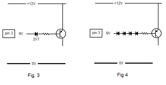
The two easy remedies are shown in the next diagram.

fig34.gif


I think they are self explanatory.
 

No we certainly don't.


If we were to connect them in the same way they wouldn't achieve the same end!

This first diagram shows the skeleton output circuit of the 555. Ideally, one or other of the two transistors will be on, the other off, at any one time. And ideally, the output will be either at 0V or, in this case, 12.

fig1.gif


But we know that the output won't necessarily be quite at 12V, and may be inconveniently lower, as in the next diagram.

fig2.gif


The two easy remedies are shown in the next diagram.

fig34.gif


I think they are self explanatory.

Thanks mate, but I was mulling it over while I was spraying weeds today and the penny finally dropped.

In the case of ordinary diodes, you would reverse bias them relative to the 555.

I already know, from my use of them as a means of clipping an AC signal, that they will conduct current only when the voltage diff between the two ends exceeds their combined foward voltage drop.

So it is the same deal as with the zener. The only way they will conduct current from the BC327 to the 555 is when the voltage diff exceeds their combined foward voltage, which can only occur when the 555 is low.

Nothing is more satisfying than when comprehension of a difficult concept finally dawns.
 

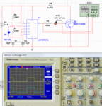
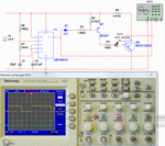
I don't know why the design needs Q1 really. The peak current into the base of Q2 is only 60mA. This is well within the capability of a TTL type 555. It would be easier to just alter the duty cycle of the 555 and drive Q2 directly.
 

Attachments

  • 555_switch.gif
    555_switch.gif
    113.4 KB · Views: 63
  • 555_switch1.gif
    555_switch1.gif
    138.4 KB · Views: 57

I don't know why the design needs Q1 really. The peak current into the base of Q2 is only 60mA. This is well within the capability of a TTL type 555. It would be easier to just alter the duty cycle of the 555 and drive Q2 directly.

Well that has puzzled me as well, but more along the lines of why a PNP signal inverter. Why couldn't they have used BC337 for example?
 

Base-emitter current.


It affects the BC327's collector-emitter current. (Check your dictionary and compare affect and effect.)


The simplest thing to do is add a couple of diodes, or a zener, in series with the base and the 555's output pin. With your 12V supply, adding a 4V7 zener, for example, would mean that the 555's output would have to drop below 5-and-a-bit to switch the BC327 on.

You may want to change the series R to suit, so that your desired BC327 base-emitter current figure is maintained.

I have just tried this suggestion, I used a 5.1V zener and it still does not work.

If I divert my BC327 output to my diagnostic LED and use a 2200uF time capacitor then I still fail to see any oscillation - the LED still remains permanently lit.

Surely that can only mean that the BC327 is incorrectly biased with a 2.2k resistor and is not switching off enough to make any oscillation discernible with the naked eye?
 

Check your circuit. You are doing something wrong.
 

Check your circuit. You are doing something wrong.

This circuit? Or one of the circuits posted by others?

This circuit is the origianl design that came with the kit I bought. Can you elaborate what you think is wrong about this design?

**broken link removed**
 

Are you sure you have the zener connected the right way around? The only way Q1 won't switch off is when the base is not pulled high enough.
 

Are you sure you have the zener connected the right way around? The only way Q1 won't switch off is when the base is not pulled high enough.

Well I actually tried the zener both ways and it makes no difference. Either way I can see no oscillation on the diagnostic LED.

I am going to try doing the transistor bias calculations from scratch and see what resistor values I come up with, combined with the zener.

I have done this once before with a HR tv transistor and the same circuit layout and got the thing working as I would expect, with an automotive light bulb in place of the ignition coil.
 

What happens if you leave the base disconnected? Is the led off then?
 

Status
Not open for further replies.

Part and Inventory Search

Welcome to EDABoard.com

Sponsor

Back
Top