Continue to Site

Welcome to EDAboard.com

Welcome to our site! EDAboard.com is an international Electronics Discussion Forum focused on EDA software, circuits, schematics, books, theory, papers, asic, pld, 8051, DSP, Network, RF, Analog Design, PCB, Service Manuals... and a whole lot more! To participate you need to register. Registration is free. Click here to register now.

analysis for 100w amplifier ciruit

Status
Not open for further replies.

mr_byte31

Full Member level 5
Joined
Oct 19, 2005
Messages
295
Helped
10
Reputation
20
Reaction score
8
Trophy points
1,298
Activity points
3,241
analysis for 100w ciruit

Hi all
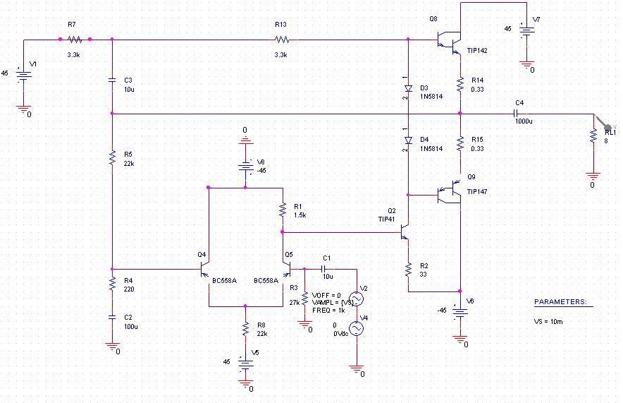
I found this ciruit on the net
most people say that it works very fine and with a good quality
here is the main link : **broken link removed**
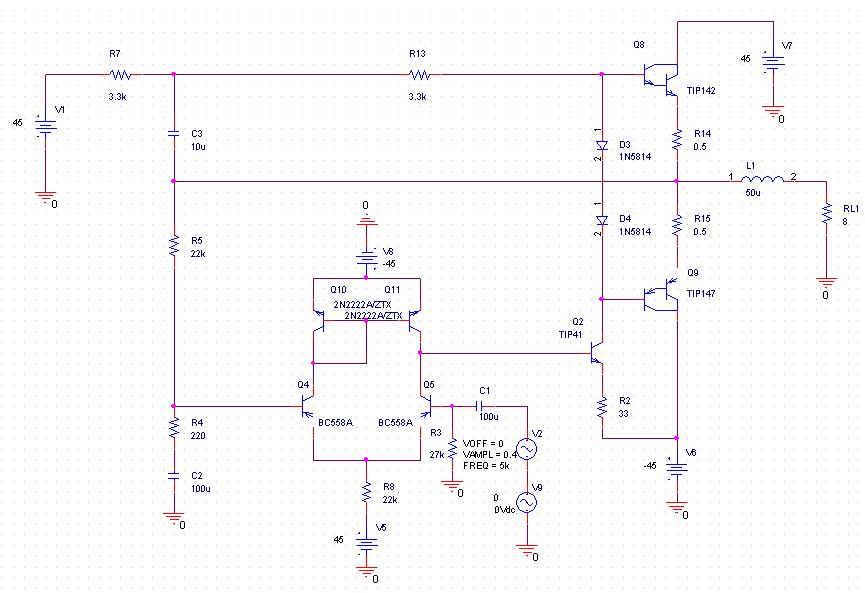
I attached ciruit with transistors so it can be easily seen
I made simulation to it and it seems great
i want to make analysis to it so i can modify it
I have a little problem with it
in the positive peak the power is 113 watt and the negative peak the power is 111 watt
I think it will not be noticed but I am seeking to solve this
any suggestions for analysis and my problem
 

Re: analysis for 100w ciruit

Many people can´t tell the difference between AM and FM radio. For those people this circuit may sound fine. With this circuit you´ll get:
1- Bad frequency and transient response
2- Lots of distortion (class-B output, low open loop gain)
3- Less power than you are expecting unless you have a regulated power supply.
It´s a waste of time (just as horrible as the shown diagram).
Regards
 

analysis for 100w ciruit

I made simulation and found the frequecny response is very good
the bandwidth is from 20Hz to 100k
the gain is high
when the input is 0.3V the output will be about 28v or more i think it is high
I think it is very big I can limit it to 20Hz to 20K using 0.1mH coil
doesn't it seem a good circuit
I think there is no problem to make the power supply mentioned in the circuit link

I can't understand the problem of distortion I can see the output signal without distortion and very smooth
could u plz explain?
 

Re: analysis for 100w ciruit

I doubt you can get this freq. response but if the simulated result is good for you it is OK. The problem with distortion is that, as any class-B amp, the output transistors are not biased for low amplitude signals and crossover distortion will arise. Please refer to this post
#1199166
Regards
 

    mr_byte31

    Points: 2
    Helpful Answer Positive Rating
Re: analysis for 100w ciruit

I made simulation to it and it seems great
You apparently didn't simulate distortion. It's pretty easy with SPICE fourier analysis. I see about 6% THD at 1kHz/1V output voltage with 4 ohm load.

I agree, that the frequency response is O.K.
 

analysis for 100w ciruit

1khz and 1v this is a very large input signal
try any thing under 0.4v and see the signal quality
the circuit starts to clip the signal over 0.4v
 

analysis for 100w ciruit

Look sharp. I said 1 V output voltage. (Means 10 mV input)
 

analysis for 100w ciruit

could u plz explain how did u simulate distortion??
is 6% huge number?
 

analysis for 100w ciruit

I apply a VSIN input source in transient analysis with fourier analysis of the output voltage. The total harmonic distortion is calculated directly.

6% THD is quite a lot. It's even higher with lower output voltage. As pauloynski pointed out, the class-B operation mode (zero bias current) and low loop gain are the reason for high distortions.
 

analysis for 100w ciruit

thanks a lot man
do u recommend any cheap good quality circuits??
I need 200W one with a good quality

can u help for that?

Added after 1 minutes:

I found this one : **broken link removed**
whats ur idea about it too :)

Added after 4 hours 40 minutes:

FvM said:
I apply a VSIN input source in transient analysis with fourier analysis of the output voltage. The total harmonic distortion is calculated directly.

6% THD is quite a lot. It's even higher with lower output voltage. As pauloynski pointed out, the class-B operation mode (zero bias current) and low loop gain are the reason for high distortions.
isn't there any idea to solve this problem?

Added after 30 minutes:

I found something when i remove the Resistance
which is connected to the 45v and with 3.3k value
the distortion decrease at 10mv input to 4%
its name is R7 in the updated image here
 

analysis for 100w ciruit

The simple amplifier has very high horrible distortion.
Make an IC amplifier or make a much better one.
 

I have modified the circuit
here it is :

the distortion now is around 1%
I think this is better
I want you idea about the new modifications I did
thanks in advance :)
 

A good power amplifier has distortion of 0.05% or less at any power up to full output at all audio frequencies from 20Hz to 20kHz.

The 200W car amplifier you found (a car with a 24V battery?) produces 200 Whats into 2 ohms or about 80 watts into 4 ohms or 50 Watts into 8 ohms.
 

0.05% Ohhhhhh
then is there any chance to enhance my circuit?
the other question
from where does the distortion come from?
 

Your amplifier circuit is too simple.
The output darlington transistors are not biased enough so they produce crossover distortion.

The other transistors should make an opamp that has distortion of only 0.003% or less.
 

I can see the input sin signal very clear
i think the crossover distortion of the darlington is minimum as possible because of the negative feedback removes it
am I right?
 

In my opinion the distortion is minimum when you use a couple of Sziklai pair in the output stage (or CFP complementary feedback pair) which guarantee a 100% feedback
 

    mr_byte31

    Points: 2
    Helpful Answer Positive Rating
ok i will give it a try
but which transistors should I use ?
could you give me some numbers?
 

Of course, but they are not so cheap. For the drivers you can use 2SC2238 and 2SA968 (respectively for pull-up an pull-down net) while for the outputs you can use 2SA1216 and 2SC2922.
 

    mr_byte31

    Points: 2
    Helpful Answer Positive Rating
Status
Not open for further replies.

Similar threads

Part and Inventory Search

Welcome to EDABoard.com

Sponsor

Back
Top