Continue to Site

Welcome to EDAboard.com

Welcome to our site! EDAboard.com is an international Electronics Discussion Forum focused on EDA software, circuits, schematics, books, theory, papers, asic, pld, 8051, DSP, Network, RF, Analog Design, PCB, Service Manuals... and a whole lot more! To participate you need to register. Registration is free. Click here to register now.

Analysing Rectifier input and output waveforms

Status
Not open for further replies.

saonibanerji

Newbie level 6
Newbie level 6
Joined
Oct 10, 2012
Messages
14
Helped
0
Reputation
0
Reaction score
0
Trophy points
1,281
Location
Singapore
Visit site
Activity points
1,363
Analyzing Rectifier input and output waveforms

Hi Guys,

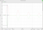
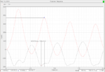
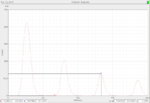
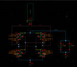
I am simulating a cross- coupled rectifier and need help in analyzing the input and output rectifier waveforms for correcting the circuit.

Need Help!!

Thanks,:smile:
 

Attachments

  • Picture1.png
    Picture1.png
    43.7 KB · Views: 106
  • Picture2.png
    Picture2.png
    53.3 KB · Views: 115
  • Picture3.png
    Picture3.png
    39.6 KB · Views: 99
  • Rectifier.png
    Rectifier.png
    93.5 KB · Views: 115
  • cmut.png
    cmut.png
    19.1 KB · Views: 113
Last edited:

I don't understand your circuit. You have the signal going to the MOSFET gates but nowhere else. How do you expect a signal on the output?


The output voltage waveforms should be that of an ideal full wave rectifier. But It is not so ( illustrated in the third snapshot) I need to analyse and correct the circuit specifications accordingly to receive the correct output waveforms
 

I added coupling capacitors and the output voltage is regulated now. However the PCE is very low. Could anyone suggest me an idea to increase the PCE?
 

Status
Not open for further replies.

Part and Inventory Search

Welcome to EDABoard.com

Sponsor

Back
Top