MisterBeppe
Junior Member level 2

- Joined
- Feb 27, 2015
- Messages
- 23
- Helped
- 0
- Reputation
- 0
- Reaction score
- 0
- Trophy points
- 1
- Activity points
- 232
Hi,
I wish some help with the following circuit:
**broken link removed**
The purpose of the following circuit is to generate a sawtooth waveform, to continuously change the value in pF of these varactor diodes (these diodes replace a manual variable capacitor in a tank circuit, to feed a sweep oscillator).
The point is the following: currently, using this circuit, the sawtooth waveform change the value from about 0 V to about 8 V; but these varactor diodes need a max value of 28 V, to fully cover their pF range (at about 28 V these varactor diodes achieve their minimum pF value).
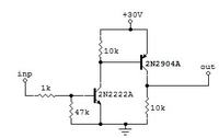
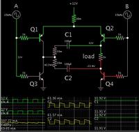
I was thinking to add a transistor or an opamp to the sawtooth output (the R4 resistor, however, must stay present before the diodes), to increase the max volt value (so from 0 to 28/29 V): this option would be a viable way? And if so, can I have some suggestions about how to implement this solution?
I can also consider to adopt another circuit, considering that I prefer if the power supply of the circuit itself would not exceed the value of 12 volt.
Many thanks.


