Continue to Site

Welcome to EDAboard.com

Welcome to our site! EDAboard.com is an international Electronics Discussion Forum focused on EDA software, circuits, schematics, books, theory, papers, asic, pld, 8051, DSP, Network, RF, Analog Design, PCB, Service Manuals... and a whole lot more! To participate you need to register. Registration is free. Click here to register now.

amplify really smal sine to TTL levels (with smd)

Status
Not open for further replies.

rompelstilchen

Full Member level 2
Joined
May 22, 2010
Messages
122
Helped
0
Reputation
0
Reaction score
0
Trophy points
1,296
Location
fdsf
Activity points
2,308
hello,

i have a 0.25v peak to peak sine with a 2.2Vdc (coming out of an ir detector, in a self made wheel encoder)
and i need to turn this to ttl mfor a microcontroller

i used a shmitt trigger, but the signal is so small, that it does not work
so i thought using a comparator (lm393, but the minimum voltage had to be 0.4v)

so i wanted to use a transistor, but as there are infos of how to calc values to amplify a signal
there is nothing about turning a small sine wave to TTL

i guess i have to amplify the signal so it clips, but what value for the input capacitor and the surrounding resistors ?
also the whole thing has to be small so i need to use smd (something like BC846/7/8...)

anyone can enlight me ?

appreciate
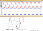
 

hi,
A LM393 will detect switching levels much lower than 0.4V, this circuit has a +/-0.1V sine wave superimposed upon a +2.5V DC level.
E
 

Attachments

  • AAesp02.gif
    AAesp02.gif
    46.1 KB · Views: 108

Hi,

really small sine... I thougt of microvolts.

go for LM324, *edit: not LM324! it must be LM393. sorry
or especially look for a comparator with common voltage input levels down to gnd.

The problem might be the 2.2VDC. is it stable, so you can rely on it?

Wheel encoder manufacturers often use a signal that is 180° phase shifted and compare both signals.
Usually the DC drifts on both signals so it cancels itself.


Klaus
 
Last edited:

thx,

but it's a lot of peripheral components,

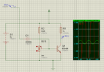
from this video (https://www.youtube.com/watch?v=eKHKGpOcllA), I made a simulation with 1 cap, 3 res and a smd transistor

EDhdR1Y.png

but i dont know if it will work as expected

now i hesitate with between mine and yours, lol :)

- - - Updated - - -

- - - Updated - - -

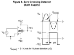
yes i meant the lm393 datasheet show this

schema2.png

with a 0.4v min Vin, that's why I wrote small voltage
 
Last edited by a moderator:

yes i meant the lm393 datasheet show this
with a 0.4v min Vin, that's why I wrote small voltage
I think you are quoting the description of a specific application circuit without understanding it's meaning.

The explanation is referring to a 1% phase error criterion. That's a rather tight specification which seems unrelated to your application. If you think about it a bit, you'll realize that the 400 mV level has to do with comparator offset voltages.

If you have similar strict phase error requirements and low signal level (I don't think so), you either need a comparator with lower offset voltage or a preamplifier.
 

yes i was not quiet sure,
anyway i tried with a transistor, and of course it is not working :)
i am screwed
 

Hi,

about schematic of post#4:

I don´t think it is possiblewith that circuit, because your signal frequency is variable and goes down to 0.
At least with an encoder and RPM = 0.

Klaus
 

well i tried before with a cd4093(smitt trigger) but i had no square output

besides my mottors have a constant speed so the frequency is stable but hard to say what frequency(it is i a gearbox)
 
Last edited:

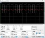
Well I think this circuit should solve your problem. (See attachments)
I have simulated it successfully down to 1Hz

Eda3.JPG

Eda2.JPG
 

thx, i'll give it a try
but what is the part used ?

here is a picture of a board that uses transistors, so it should be possible:

Rover5Encoders130110a.jpg

- - - Updated - - -

hi,
A LM393 will detect switching levels much lower than 0.4V, this circuit has a +/-0.1V sine wave superimposed upon a +2.5V DC level.
E

hello,

did you test the circuit ? is it working ?

(cos i just spend money on stuff that dont, one can't definetely rely on a simulation
those bc848 transistors i bought are crap)
 

I was never impressed by the BJT idea.
1. As already stated by Mr. Klaus, failure is inevitable at low speeds.
2. BJTs require significant input current, which the encoder may not be able to provide.

Write down the equations for the OP-AMP circuit shown above and fine tune the values of R and C according to your needs. I do not see why this circuit should not work.
 

Well I think this circuit should solve your problem. (See attachments)
I have simulated it successfully down to 1Hz

View attachment 107604

View attachment 107605

You should make R2 a pullup to Vcc, since the output from LM393 is an open collector. You should also be aware that the max input voltage below GND or negative supply is -0.3V. Below that, the functionallity will suffer.
 

You should also increase the value of R2.
If you need a true standard TTL input current levels, you may have a problem with pulling the signal low with a sink current of 6.6mA. If you increase the R2 to 2k2 or 4k7, you should be good. If you use LS circuits, you should be good with 4k7. With HC you can increase to 10k.
 

i have failed to make work all proposed setup , but...
it finaly worked with an lm393 with a 10k pull up resistor and nothing more
i am still going to try amplify the signal with a transistor cos smd pots (vref) are really not precise and seem unstable

maybe unless i glue them

anyway thx for the precious help eveyone
 

Status
Not open for further replies.

Similar threads

Part and Inventory Search

Welcome to EDABoard.com

Sponsor

Back
Top