Continue to Site

Welcome to EDAboard.com

Welcome to our site! EDAboard.com is an international Electronics Discussion Forum focused on EDA software, circuits, schematics, books, theory, papers, asic, pld, 8051, DSP, Network, RF, Analog Design, PCB, Service Manuals... and a whole lot more! To participate you need to register. Registration is free. Click here to register now.

Amplifier gain not stable

Status
Not open for further replies.

lichengjun

Junior Member level 2
Joined
Dec 21, 2015
Messages
24
Helped
0
Reputation
0
Reaction score
0
Trophy points
1
Activity points
261
I found an amplifier board which was made by someone else several years ago.
amplifierboard.png
The function of this board is to amplify the output signal of a linear displacement sensor in a tensile testing system.
The schematic is shown below.
schematic.jpg
The ideal gain is 213.765 by using the equation Vout = (V+ - V-) *(R1+R2)/R2 with R4=R1 and R3=R2.
However, I made a simple measurement and found that as the input voltage(V+ - V-) increases, the gain decreases.
gain vs input voltage.png

There are two sets of instrumentation amp in this board, I test both, and they both show above phenomenon. So I don't think it's the board's problem, I think there must be something I did wrong which lead to this strange result.

The steps I did are like following:
1. I connect the excitation input of the linear displacement sensor to 5V power supply.
2. I connect the signal output of the linear displacement sensor to the V+ and V- of the amplifier board.
3. I power the amplifier board with a 12/-12V dual power supply.
4. I connect the 12/-12V power supply's ground to the ground of 5V power supply.
5. I change the signal output of the displacement sensor(input to the amplifier board) and measure the output of the amplifier board, then calculate the gain.

Could anyone tell me what I did wrong? Why the gain is not stable?

Thanks.
 

The ideal gain is 213.765 by using the equation Vout = (V+ - V-) *(R1+R2)/R2 with R4=R1 and R3=R2.

Unless I am wrong, Vout/(V+ - V-)=(R1+R2)/R2=(10^6+47*10^3)/47*10^3=22.276595

Your gain 213.765 is if using 4.7k resistors.
 
Last edited:
Unless I am wrong, Vout/(V+ - V-)=(R1+R2)/R2=(10^6+47*10^3)/47*10^3=22.276595

Your gain 213.765 is if using 4.7k resistors.

I am so sorry, R1=R4=10M actually. Any idea about the gain decreasing?
 

Hi,

Maybe it's just an offset problem.

First you need to input 0V and read the output (offset).
Then for all the other input voltages yiu need to subtract the initial output offset voltage.

...
If this is not the problem..
Maybe you could tell us how exactely you measured your values.
..and what measuremen devices you used..how reliable are the mV readings?

Klazs
 
You cannot use a resistor with a value as high as 10M in a circuit that uses lousy old LM324 opamps as in your photo. Your schematic uses better opamps. Which opamps are you using?
Are the resistors cheap from "over there" or are they good ones?
 

You cannot use a resistor with a value as high as 10M in a circuit that uses lousy old LM324 opamps as in your photo. Your schematic uses better opamps. Which opamps are you using?
Are the resistors cheap from "over there" or are they good ones?

The omamp is LM324.
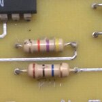
I am not sure whether they are good ones. I took a closer picture of the resistors.
IMG_0770.JPG
Based on color code on the resistor, I can tell it has 5% tolerance. Not sure whether it's good enough.
 

The cheap LM324 opamps are horrible in that circuit and the resistors are cheap carbon film and look damaged. The opamps in the schematic are much better and undamaged metal film resistors are more stable.
 

The cheap LM324 opamps are horrible in that circuit and the resistors are cheap carbon film and look damaged. The opamps in the schematic are much better and undamaged metal film resistors are more stable.

Thanks for the reply. I will try using better components. But I am still a little confused, will the cheap LM324 opamp or the cheap resistor lead to the unstable gain? I would think it might lead to a gain much different than theoretical value, but should still be stable.
 

The high value resistors will generate noise which would be amplified. The input bias current of the chip will also fluctuate and as it flows through these resistors will also cause problems. If you need a gain of 200, split this into two parts, say 15 times (twice) so change the resistor from the -ve input to earth to 47K and the resistor from the output to the negative input to 680K. It should help a bit.
Frank
 

Hi,

The dc gain of the opamp generates up to 1% gain error at a gain of 250.
The bias current adds 1% error per 1kOhm source resistance at 5mV input voltage.

But I expect the most errors are caused by your gain tests.
* incorrect voltage readings
* thermocouple effects
* source impedance
* no offset correction
...
To verify your results we need to know how exactely you did the measurement..

Klaus
 

Although the resistance level in the original circuit is quite high for LM324, offset current is still less than one-tenth of offset voltage effect. In so far there's no sense in changing the resistors without the OP type.

With the present resistor values, some excess noise over already high LM324 noise is generated. You would reduce R2/R3 to 1k or below with LM324 and to 100 ohm for a real low-noise OP (e.g. OP07/OP27).

If you want considerable better DC accuracy, you need a low voltage OP.
 

Hi,

Maybe it's just an offset problem.

First you need to input 0V and read the output (offset).
Then for all the other input voltages yiu need to subtract the initial output offset voltage.

...
If this is not the problem..
Maybe you could tell us how exactely you measured your values.
..and what measuremen devices you used..how reliable are the mV readings?

Klazs

You are very correct, it is the offset problem. when the input is 0V, there is 43mV output. I test again, and subtract the initial offset and got the following result. It improved a lot.
360反馈意见截图16230316365258.jpg
 

Status
Not open for further replies.

Similar threads

Part and Inventory Search

Welcome to EDABoard.com

Sponsor

Back
Top