Continue to Site

Welcome to EDAboard.com

Welcome to our site! EDAboard.com is an international Electronics Discussion Forum focused on EDA software, circuits, schematics, books, theory, papers, asic, pld, 8051, DSP, Network, RF, Analog Design, PCB, Service Manuals... and a whole lot more! To participate you need to register. Registration is free. Click here to register now.

Amplifier and filter circuit explanation

Status
Not open for further replies.

jpglotzer

Newbie level 5
Joined
Apr 15, 2011
Messages
10
Helped
0
Reputation
0
Reaction score
0
Trophy points
1,281
Activity points
1,395
Hi,

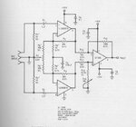
I'm building this circuit. I get what some of it does, but I'm trying to fully understand the exact purpose of EVERY component, and why that exact size capacitor or resistor was used.

ece5030 plethysmograph

I get that the 10uF with the 20kohm is a high pass filter. How do I calculate the cut off frequency, and why that frequency was chosen? I think the 100K and 1K resistors determine the gain right? If i'm correct, it's just a ratio, so the gain is 100...

I don't get what the 0.47uF capacitor in parallel with the 100K resistor does..and I don't know why that value was chosen.

And the variable resistor from 1 to ground.. if I just kept that as a 10kohm resistor.. what does that do?

Ok, i think that's pretty much it. I'm sorta struggling with this, I've found similar circuits in textbooks, but they're all slightly different, so it doesn't seem 100% relevant. Any help would be much appreciated! Thanks!
 

I shouldn't be too concerned with the exact values of some of the components.
For example, the use of 20K resistors instead of the more easily obtainable value of 22K adds unnecessary complication. Especially, as you say, when use in conjunction with the 10uF capacitors, which can have a tolerence of +80 /-20% in some cases!

Although that capacitor/resistor configuration can be used as a high pass filter, it's not in this case. You can find the cutoff frequency from the formula given here :High-pass filter - Wikipedia, the free encyclopedia , and I think you'll find it's pretty low!!
No, these capacitors are simply 'AC coupling' the amplifier stages, to allow high AC 'signal' gain, without incurring too much DC offset gain.
As for the 0.47uF capacitors across the 100K resistors, these are simply to create an active low pass filter. Again, you can calculate the frequency from here: Low-pass filter - Wikipedia, the free encyclopedia Check out the 'active low-pass filter' diagram.

The 10k pot allows you to vary the amount of signal going into the second amplifer stage. With the considerable gain introduced by the two stages, you may need to reduce the input to prevent overloading the second stage. Not that it would do any damage, simply 'clip' the signal.
You cannot simply replace it with a resistor. There would be no input to the second amplifier! You could use two resistors -say 2 x 4K7, or 6K8 and 3K3 -to 'simulate' the pot in a fixed position. Fitting the pot should probably be tried on the initial breadboard prototype, to allow you to get an idea of where your signal level is!
 
Thanks!

When you the capacitors are simply 'AC coupling' the amplifier stages, wouldn't a high pass filter have the same effect? The DC component is effectively just an AC signal with frequency 0Hz, so a high pass filter with a very low cut off frequency would just be taking away the DC component. What I'm not quite sure about is that... the cut off frequency is f=1/(2*pi*R*C). Many different combinations of R and C can give the same cut off frequency. So how do I justify choosing specifically 20K and 10uF?
 

... so a high pass filter with a very low cut off frequency would just be taking away the DC component. What I'm not quite sure about is that... the cut off frequency is f=1/(2*pi*R*C). Many different combinations of R and C can give the same cut off frequency. So how do I justify choosing specifically 20K and 10uF?

Yes - having a high gain circuit with the DC component amplified to the same extent can, as you can probably imagine, cause 'offset' havoc!

As to the choice of components. As I say, 10uF capacitors are usually electrolytic, which often have a wide range of tolerance, so are not usually used where accuracy is required.
Choosing which combination of components will often come down to the range of impedance best suited to your proposed circuit. There are no hard and fast rules.

Typically, I would suggest you would probably select values to suit this kind of circuit, from within the range 1K to 100K.

Significantly lower than 1K? - filter capacitor values can start getting very large, and you start approaching the max drive capability of the opamps.

Significantly higher than 100K? -- at very high impedance, you can start to get problems with 'stray' capacitance in PCB track or strip board layouts, and leakage currents from some capacitors.

As I say, there are no 'hard' rules. Practical experiment and experience are often the best instructors here . Try a particular variation, and see how it works out!!

Sometimes, published data doesn't always help. The attached extract from an old National Semiconductors audio handbook illustrates the kind of thing I mean.
R13 is shown as 93.1K 1% resistor. R14 is a 10k variable resistor in series with R13.
So the value can be calibrated to any value anywhere between 93169R and 104.031R (+/- the tolerance of R14)!
No real reason to specify R13 as a '1%' resistor here, I would suggest??
But very confusing when you are first starting out, and tend to trust what you read in published data.

When I first started experimenting, especially with audio circuits, I would start from the premise: 'all resistors are 10K, until proved otherwise'. Nice 'medium' impedance to work from!
A bit simplistic perhaps, but it helped me learn quite a lot!!
 

Attachments

  • var.adj.jpg
    var.adj.jpg
    40.3 KB · Views: 110
If you doubt the selected component values, simply click the first link on the page top and get a second, different set of values for the same circuit. Do you know if one is significantly better than the other?
 

Status
Not open for further replies.

Similar threads

Part and Inventory Search

Welcome to EDABoard.com

Sponsor

Back
Top