Continue to Site

Welcome to EDAboard.com

Welcome to our site! EDAboard.com is an international Electronics Discussion Forum focused on EDA software, circuits, schematics, books, theory, papers, asic, pld, 8051, DSP, Network, RF, Analog Design, PCB, Service Manuals... and a whole lot more! To participate you need to register. Registration is free. Click here to register now.

am i damaging my breadboard?

Status
Not open for further replies.

dl09

Full Member level 4
Joined
Feb 12, 2020
Messages
226
Helped
2
Reputation
4
Reaction score
1
Trophy points
18
Activity points
1,692
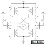
i built a h-bridge out of 4 transistors. 1 is an npn transistor. the other 3 are pnp transistor. i connected the h-bridge to a arduino uno microcontroller board. i connected a
hobby electric motor to the h-bridge. i test this circuit many times, the arduino uno microcontroller board will change the polarity of the electric motor. i have not
connected the base of any transitors to any resistors. i did not install any resistors in this circuit. the breadboard has two sets of rails. i think 1 set won't work and the other
set will work. i noticed today 1 transistor did not seem to be working then i moved it to a different spot and it seem to be working now. i am worried i am damaging the breadboard. am i?
--- Updated ---

here is a schematic
Drawing.jpeg
 

i am damaging the breadboard. am i?

Breadboard contacts are made of thin metal (from what I can tell). They might tolerate an Ampere.

You risk killing components when you omit safety resistors.

It's easier to operate a full H-bridge by making it from 2 NPN and 2 PNP. You need to experiment with bias voltages and polarities, in order to make the transistor drive a load sufficiently.
 

Hi,

No reistors, no capacitors .... how (do you think) it can work?

There are free tools to draw a schematic.
There are free simulators.
There are free Ground symbols. ;-)

Use them.

Klaus
 

what if i connect a transistor to an electric motor without connecting a resistor to the base, what would happen?
--- Updated ---

just trying to learn how to do?
--- Updated ---

just trying to learn how to do this.
 

Consider that there is a PN junction between the base and emitter (effectively it looks like diode) so it has a Vf of around 0.65V. Without resistors you are holding the Arduino outputs to the lower transistors at that voltage and almost certainly overloading the Arduino pins. For the top transistors, consider that to make them conduct you need to raise their base voltage to about 0.65V above their emitters, what voltage is there on the emitters? (hint - what makes the motor operate)

Brian.
 

i tried using ltspice. i could not find a symbol for a electric motor. how do i simulate a transistor turning on an electric motor with ltspice?
 
Hi,

Most basic for electrics and electronics: Ohm´s law.

V: What motor voltage do you expect?
I: What motor current do you expect?

Then use Ohm´s law to find out equivalent resistor value.

Klaus
 

Consider that there is a PN junction between the base and emitter (effectively it looks like diode) so it has a Vf of around 0.65V. Without resistors you are holding the Arduino outputs to the lower transistors at that voltage and almost certainly overloading the Arduino pins. For the top transistors, consider that to make them conduct you need to raise their base voltage to about 0.65V above their emitters, what voltage is there on the emitters? (hint - what makes the motor operate)

Brian.
i am using a 3 volt battery. the emitter is connected to the positive terminal , does that mean the voltage at the emitter is 3 volts?
 

I use Microsoft Paint program to copy transistors, resistor and capacitor symbols from Google Images or datasheets then paste them into a Paint circuit. Straight lines can be drawn as wires. The ground and battery symbols are also copied and pasted.
It looks like this (I also copied and pasted the motor symbol from somewhere):
 

Attachments

  • h-bridge transistors.PNG
    h-bridge transistors.PNG
    12.3 KB · Views: 118

I am planning to use ltspice to simulate a transistor turning on a motor. I once touched the positive terminal to the negative probe of the multimeter and touched the negative terminal to the positive probe, I got a reading of 628 ohms. Should I write 628 ohm, when specifying series resistance of battery?
 

Your transistors have no part numbers.
You make no sense:
1) The positive terminal of what? The motor?
2) The negative terminal of what? The motor?
3) 628 ohms is too high for a little 3V motor.
4) Was the battery disconnected?

A battery has an extremely low internal resistance until it is weak or dead.
The bases of the transistors need a series resistor added so that they or the Arduino are not overloaded and destroyed.
The resistor value is simply calculated from Ohm's Law.
The circuit I showed uses values calculated for a 3A motor and in the circuit with a 12V supply.
 

How do I measure the resistance of the battery? Please tell me. I am trying to learn how to design and build electronic circuits.
--- Updated ---

Your transistors have no part numbers.
You make no sense:
1) The positive terminal of what? The motor?
2) The negative terminal of what? The motor?
3) 628 ohms is too high for a little 3V motor.
4) Was the battery disconnected?

A battery has an extremely low internal resistance until it is weak or dead.
The bases of the transistors need a series resistor added so that they or the Arduino are not overloaded and destroyed.
The resistor value is simply calculated from Ohm's Law.
The circuit I showed uses values calculated for a 3A motor and in the circuit with a 12V supply.
I meant the negative terminal of the battery. I meant the positive terminal of the battery.
 

You must NEVER try to measure the resistance of a battery with a multimeter set to measure ohms. It could damage the multimeter.
The Resistance measurement of a multimeter uses its internal battery voltage.

The datasheet for a CR2032 3V battery (your battery also has no part number) shows that its resistance when new is about 25 ohms. When its load is 25 ohms then its voltage is half which is 1.5V. Then its load current is 1.5V/25 ohms= 60mA.
 

Hi,

As with your other threads.
We miss basic knowledge.

You say you "try to learn" ... but you don't follow our recommendations. You don't start at the beginning, you just choose random circuit doing random nonsense. This is not learning.

To me it sounds "I want to learn to drive a car" ... you randomly try different roads (electric circuits) and complain that it does not work like expected....while you don't know the basics - like how to start the car's engine (Ohm's law, voltage measurement, current measurement).
--> This way you will never make progress.
You may try as many roads you like ... but as long as you can't start the engine....it's just a waste of your (and our) time.
*****
How do I measure the resistance of the battery?
"Learning" is not to connect a DVM. And risk the DVM to catch fire.
"Learning" is to do an internet search "How do I measure the resistance of the battery" and follow the recommendations step by step.

When you go on this way...
* you will make no progress
* no other forum member will gain any information from your threads ... rather confuse them
* you will be no benefit for the forum
* sooner or later I will vote for a forum ban

So please rethink your "learning style" ... it will be your benefit.

Klaus
 

Status
Not open for further replies.

Part and Inventory Search

Welcome to EDABoard.com

Sponsor

Back
Top