Continue to Site

Welcome to EDAboard.com

Welcome to our site! EDAboard.com is an international Electronics Discussion Forum focused on EDA software, circuits, schematics, books, theory, papers, asic, pld, 8051, DSP, Network, RF, Analog Design, PCB, Service Manuals... and a whole lot more! To participate you need to register. Registration is free. Click here to register now.

alternating current circuit help

Status
Not open for further replies.

Bhuvanesh123

Advanced Member level 4
Joined
Aug 29, 2013
Messages
113
Helped
0
Reputation
0
Reaction score
0
Trophy points
16
Location
Singrauli, India, India
Activity points
814
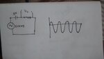
i have attached my circuit and corresponding waveform,i don't even know what my attached circuit is called as.i have 5vrms ac source c, 3v dc source ,some k ohm resistor , all are connected in series.my output waveform look like its shifted down.what operation actually going on there and how the waveform shifted down.Thank you in advance
 

Attachments

  • IMG_20150317_070201910.jpg
    IMG_20150317_070201910.jpg
    576.3 KB · Views: 60

ohh ,kvl that is that magic word i missed,thanks .
Now, 3v dc source is replaced with forward biased pn diode

Vo = 5 sqrt(2) sint (wt) -0.7V

am i right?
 

You have a D.C source which maintains a fixed potential difference between its two terminals. Because the output is taken from the lower potential side of the battery then this point will always be 3 Volts lower than the positive potential terminal of the battery. So when your sine wave (we will say it's peak to peak 10 volts) goes to the maximum positive value of 5 volts then the output must be 3 Volts lower. So the maximum output will be 2 Volts. When the sine wave goes negative then the output terminal will be 3 Volts lower still and produce -8 Volts. This is what causes the waveform to shift down by 3 Volts. This is referenced to the lower end of the A.C source.
Thanks
Adam
 

Status
Not open for further replies.

Similar threads

Part and Inventory Search

Welcome to EDABoard.com

Sponsor

Back
Top