new_rf_engineer
Newbie
Hi everyone,
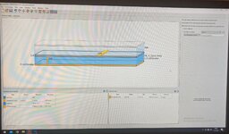
NOTE: I am using ADS almost for 6-7 months to design RF filters. I design filters and simulate them. From now on, I used 1 layer subtrates like in Fig1 for simulations.
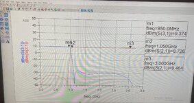
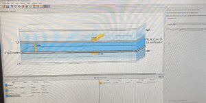
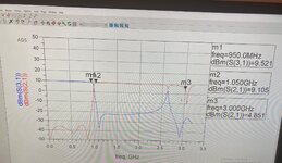
I have a circuit which includes both low pass and high pass filters. For this circuit, firstly, i used 1 layer subtrate like in Fig1. The simulation result is shown in Fig2 for that circuit and 1 layer subtrate. For the same circuit, I used 2 layers subtrate like in Fig3 and simulation result is like in Fig4.
The only thing which changes is subtrate which changes from 1 layer subtrate design to 2 layers subtrate design. What can be the reasons of changing simulation result by looking at the Fig2 and Fig4 ?
Can you give me some advices ? Thanks for advance.
NOTE: I am using ADS almost for 6-7 months to design RF filters. I design filters and simulate them. From now on, I used 1 layer subtrates like in Fig1 for simulations.
I have a circuit which includes both low pass and high pass filters. For this circuit, firstly, i used 1 layer subtrate like in Fig1. The simulation result is shown in Fig2 for that circuit and 1 layer subtrate. For the same circuit, I used 2 layers subtrate like in Fig3 and simulation result is like in Fig4.
The only thing which changes is subtrate which changes from 1 layer subtrate design to 2 layers subtrate design. What can be the reasons of changing simulation result by looking at the Fig2 and Fig4 ?
Can you give me some advices ? Thanks for advance.