Amr Wael
Member level 5
Hello ,
I created a layout for coplanar waveguide in ADS and then created an EM model and added pins, then created a symbol and ran cosimulation between schematic and EM momentum microwave. I ran the optimizer tool in ADS but my problem is that some of the jobs fail and error is
At least one port pin or bondwire end is not
fully connected to a conductive part of the
design (see the layout processing report for
details).
"
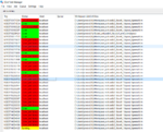
The point is that all pins are directly connected to the conductor top layer and their ground is also defined as the bottom layer. and what is confusing that not all jobs fail!
some of them succeed as shown in the attached photo. What I have in mind is that "maybe" when the optimizer tool sweeps over a different length for the line it doesn't change the size of the ground plane or the position of the pins ? but this is too dumb if that's the problem!
Any ideas about the source of this problem/possible solutions?
Thank you all very much in advance.
I created a layout for coplanar waveguide in ADS and then created an EM model and added pins, then created a symbol and ran cosimulation between schematic and EM momentum microwave. I ran the optimizer tool in ADS but my problem is that some of the jobs fail and error is
At least one port pin or bondwire end is not
fully connected to a conductive part of the
design (see the layout processing report for
details).
"
The point is that all pins are directly connected to the conductor top layer and their ground is also defined as the bottom layer. and what is confusing that not all jobs fail!
some of them succeed as shown in the attached photo. What I have in mind is that "maybe" when the optimizer tool sweeps over a different length for the line it doesn't change the size of the ground plane or the position of the pins ? but this is too dumb if that's the problem!
Any ideas about the source of this problem/possible solutions?
Thank you all very much in advance.