Continue to Site

Welcome to EDAboard.com

Welcome to our site! EDAboard.com is an international Electronics Discussion Forum focused on EDA software, circuits, schematics, books, theory, papers, asic, pld, 8051, DSP, Network, RF, Analog Design, PCB, Service Manuals... and a whole lot more! To participate you need to register. Registration is free. Click here to register now.

ADS Cosimulation handle Vias

Status
Not open for further replies.

m8888

Newbie level 3
Joined
Nov 21, 2011
Messages
3
Helped
0
Reputation
0
Reaction score
0
Trophy points
1,281
Location
Munich
Activity points
1,305
hi!
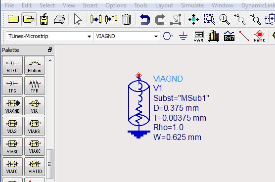
Could someone please tell me how to handle Vias in an appropriate way when setting up a cosimulation?
I'm using microstrip so I use vias to connect ground to my design.
Do I just set ports in my design and connect grounds in the schematic to it or do I use the Vias from the layout window or should I use some eqivalent circuit?

thank you very much,
m8888
 

In SCH, you should use equivalent circuits, and in layout, you should build the model.
 

Do I just set ports in my design and connect grounds in the schematic to it

This would create an "ideal" short, which does not exist in hardware.
To get physical via properties, use via models in the schematic (as tony has suggested) or better include the via in the EM model.
 

hi, thanks for your answer.
So my next problem is how to include vias in the EM model.
For the schematic I suppose I should do it this way: "a single via is a series inductance with a resistor, and a parallel capacitor to the ground."
how do I find out the dimensions?
Is there any tool or help in ADS for that?
It would be the best if I could use vias directly in the EM model. How do you usually do that?
 

For the schematic I suppose I should do it this way: "a single via is a series inductance with a resistor, and a parallel capacitor to the ground."

It's simple: use the ADS model for vias.


how do I find out the dimensions?
Is there any tool or help in ADS for that?

Just use your engineering education and try to get the current to ground with minimum inductance (shortest path).
See this presentation, pages 35-39.
https://muehlhaus.com/wp-content/uploads/2011/10/RadioTecC2011_PCB_EM_Muehlhaus.pdf

It would be the best if I could use vias directly in the EM model. How do you usually do that?

You can place vias in the EM model.
 

very interesting presentation!

Is my understanding right?:
To insert Vias there are two possibilities:
1. Insert Ports in my EM Model and then use VIAGND in the cosimulation/schematic
2. Insert VIAGND directly in the EM Model

With point 2 I'm confused:
Do I have to redefine layers? Like an additional layer called Via? And should I find this afterwards in my Layout Layers under Substrates Create/Modify?
Should I use -->Options --> Via Configurations --> Add Vias?

thanks a lot
 

Ooops. Please don't get me wrong, but you should really have some Momentum training/introduction to understand the Momentum workflow basics.
 

Status
Not open for further replies.

Part and Inventory Search

Welcome to EDABoard.com

Sponsor

Back
Top