Continue to Site

Welcome to EDAboard.com

Welcome to our site! EDAboard.com is an international Electronics Discussion Forum focused on EDA software, circuits, schematics, books, theory, papers, asic, pld, 8051, DSP, Network, RF, Analog Design, PCB, Service Manuals... and a whole lot more! To participate you need to register. Registration is free. Click here to register now.

adjusting the gain margin of a system

Status
Not open for further replies.

bharathr87

Member level 1
Joined
Jan 27, 2009
Messages
34
Helped
0
Reputation
0
Reaction score
0
Trophy points
1,286
Activity points
1,482
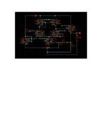
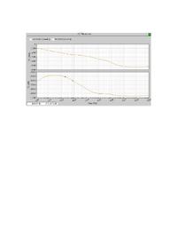
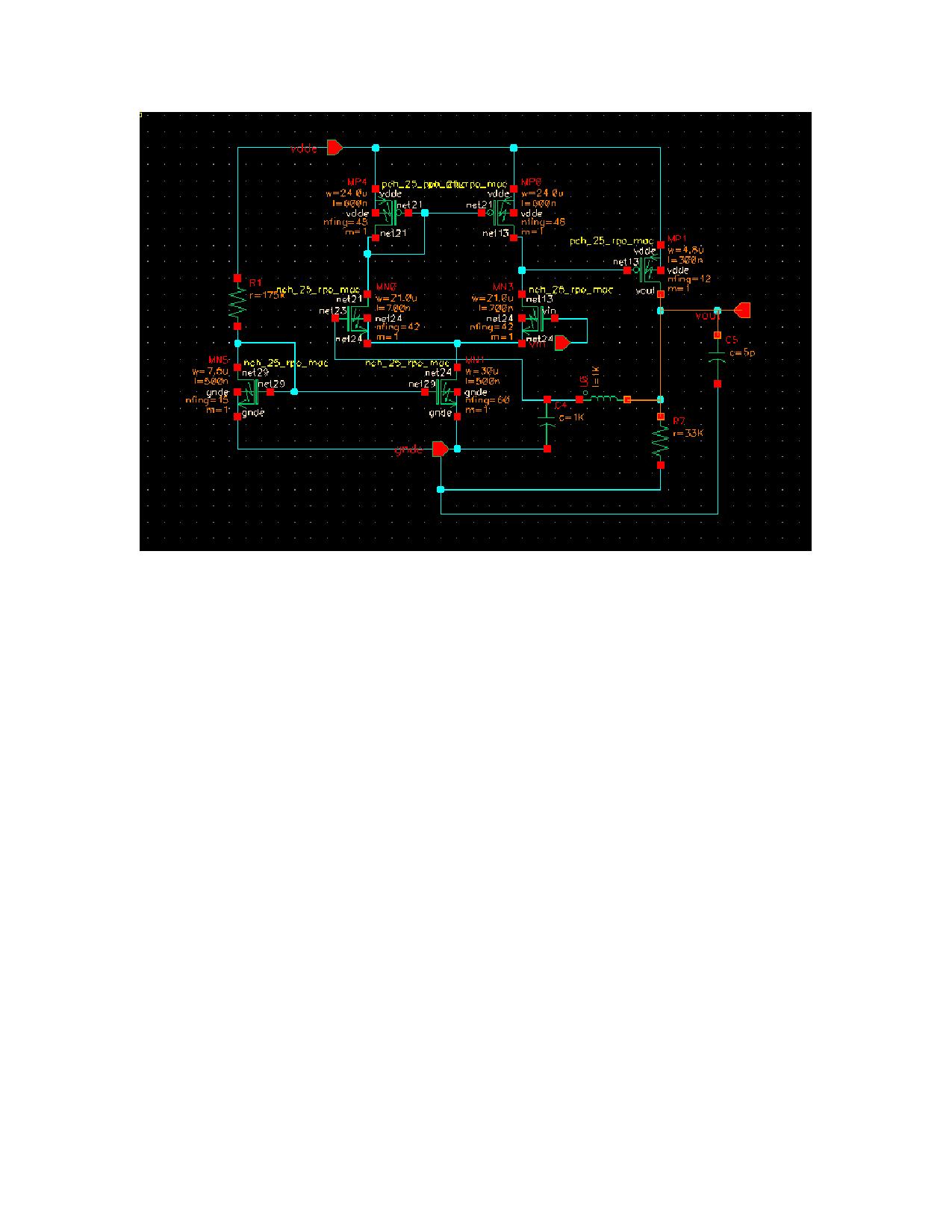
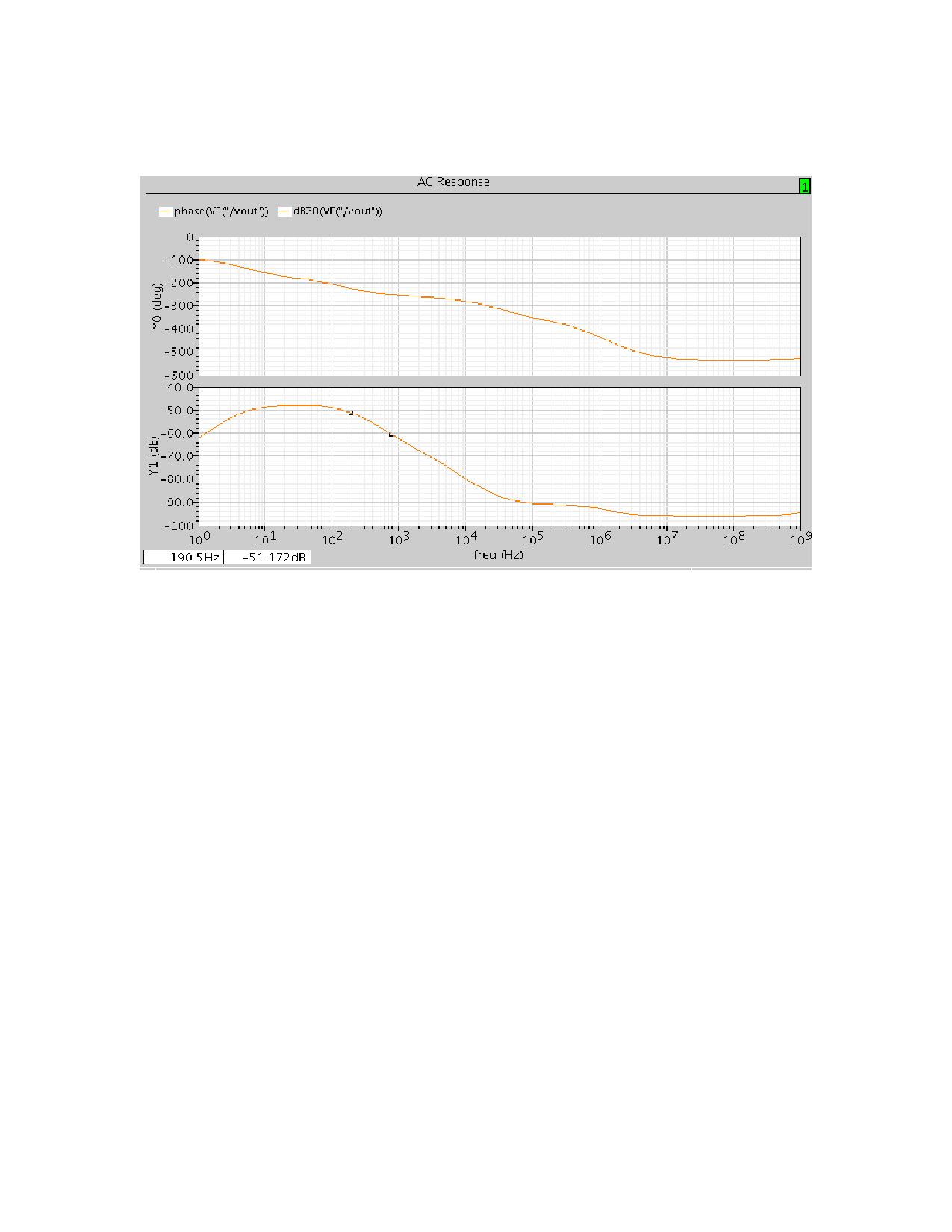
the images of the buffer amplifier ckt and its freq response(gain and phase plots) are below....it is unstable right? wat modifications do i have to do for the circuit if i hav to make it stable? the load cap. can be >=3.5pF.


Hi,
There seems to be some problem with the simulation setup. If you look at the mag and the phase plots, they don't go hand-in-hand. Near to 0Hz, the mag plot shows a +x dB roll-off, whereas the phase rolls off by -x deg. At 1K the phase plot flattens out, but the mag plot rolls off.
Please check the setup and the measurements.
I think in Gray meyer book there is a mention of the a 3-amp structure for AC analysis, instead of opening the loop using the elements.

Regards,
RDV
 

It is clear from your sim results that something is wrong. Your DC gain is negative, which is indicitive of something is not biased right or something. You should be seeing a gain of at least 40-50db with that amp. You shouldn't be seeing -50dB. Something is wrong with your setup.
 

Status
Not open for further replies.

Part and Inventory Search

Welcome to EDABoard.com

Sponsor

Back
Top