difr
Newbie level 2
Adding Status LEDs to input & output lines.... between I/O Controller & Robot
Hi
I have an existing I/O controller connected to a robot arm. I'm wondering, how can I add some status LEDs that tap into the input & output lines so I can make a little LED display for troubleshooting etc.
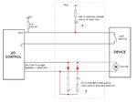
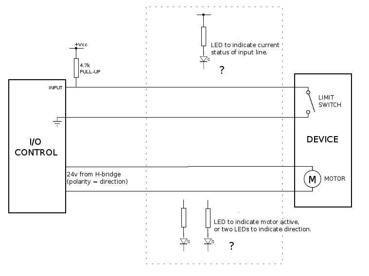
Please see my rough schematic: (only shows one switch/motor for simplicity)
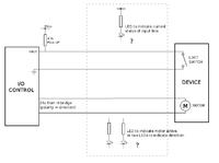
I thought I might need to use a buffer (like 7407) to isolate the LEDs, but maybe a transistor will do. Also, it's not really practical to cut into the existing input/output lines - I just want to tap off them. Also, the output lines are 24VDC 3A, so I don't want to cut into those.
So if I want to test that the input switch is working, I can manually push it and the status LED will light. It would also light during normal operation of the robot.
And a different LED would light to indicate that the motor should be running, or even an LED for each direction (forward/reverse).
Thanks for your help,
Dan.
Hi
I have an existing I/O controller connected to a robot arm. I'm wondering, how can I add some status LEDs that tap into the input & output lines so I can make a little LED display for troubleshooting etc.
Please see my rough schematic: (only shows one switch/motor for simplicity)
I thought I might need to use a buffer (like 7407) to isolate the LEDs, but maybe a transistor will do. Also, it's not really practical to cut into the existing input/output lines - I just want to tap off them. Also, the output lines are 24VDC 3A, so I don't want to cut into those.
So if I want to test that the input switch is working, I can manually push it and the status LED will light. It would also light during normal operation of the robot.
And a different LED would light to indicate that the motor should be running, or even an LED for each direction (forward/reverse).
Thanks for your help,
Dan.
Last edited: