Continue to Site

Welcome to EDAboard.com

Welcome to our site! EDAboard.com is an international Electronics Discussion Forum focused on EDA software, circuits, schematics, books, theory, papers, asic, pld, 8051, DSP, Network, RF, Analog Design, PCB, Service Manuals... and a whole lot more! To participate you need to register. Registration is free. Click here to register now.

Adding a wireless switch to a tiny camera.

Status
Not open for further replies.

jasonstatham

Newbie level 6
Newbie level 6
Joined
Sep 13, 2013
Messages
11
Helped
0
Reputation
0
Reaction score
0
Trophy points
1
Visit site
Activity points
92
Hello, my name is Jason and i have a little problem.

i have a little camera, and i would like to add 2 wireless pushbutton switches to it.

The camera has 2 buttons: one to turn the device on and off.
the second to take a picture, if you press longer it takes a video.

I would like to install these 2 switches so that when i push one of the switches it turns on the camera.
And when i push the second button that it takes a photo, and when i press longer on the switch that it takes a video.

Is this possible by opening up the device and soldering the switches to it?
Maybe this is the wrong side of the forum or the complete wrong forum.

Any help would be greatly appreciated!

Thanks :)

Jason
 

If the camera has a two switched with the said functions and you do not mind to loose the guarantee you can connect a 2 channel garage door remote opener receiver to the two switches
 

Thanks for your response!

i am really new to this world, so if you could explain that again but easier that would be great!
i dont mind losing the guarantee :).
 

use google and search for the terms: "wireless" "remote" and "switch" you can add bluetooth too. There seems to be a lot of wireless remote switches that are either for garage and/or gate control that run off of 12V or you can find bluetooth switches that run off of various voltages.

Not sure how you were planning on powering the receiver, I'm pretty sure it will be much harder to do it using the camera's battery.
 

maybe i could add some batteries to the reciever? and how big do you think the sender will be?

I planned to put the reciever in a pen so when i press the pen it presses the switch would go on and take a picture!
You think that is possible or am i dreaming and do these things only exist in movies?
 

maybe i could add some batteries to the reciever? and how big do you think the sender will be?
well the batteries will make the receiver much larger and the sender will require batteries too, unless it's like a garage remote or a car remote and runs off of a single AAA or a coin battery respectively.

I planned to put the reciever in a pen so when i press the pen it presses the switch would go on and take a picture!
You think that is possible or am i dreaming and do these things only exist in movies?
If you want the control unit in a pen (I'm assuming you mean like a ball point pen) then You'll have to use some awfully small silver oxide type hearing aid type batteries to power the transmitter. Plus you need to design a and build a custom transmitter module.
If you don't want to open up the camera (which seems the case) to wire in a remote switch, use a solenoid with a receiver module and mount that in some bracket that you can screw into the tripod mount on the bottom of the camera. You'll probably need to power the switch with a relay of some kind or a MOSFET as they can draw a bit of current.

Then again if you have some relatively common camera model like a reflex type Cannon, Minolta or Nikon, I bet you can buy a nice pre-made remote.

Regards
 
Hello, my name is Jason and i have a little problem.

i have a little camera, and i would like to add 2 wireless pushbutton switches to it.

The camera has 2 buttons: one to turn the device on and off.
the second to take a picture, if you press longer it takes a video.

I would like to install these 2 switches so that when i push one of the switches it turns on the camera.
And when i push the second button that it takes a photo, and when i press longer on the switch that it takes a video.

Is this possible by opening up the device and soldering the switches to it?
Maybe this is the wrong side of the forum or the complete wrong forum.

Any help would be greatly appreciated!

Thanks :)

Jason


I guess that your little camera is just like this :smile: :

down.jpg 5pcs-2GB-808-spy-car-keys-micro-camera_1774090_2.bak.jpg
808 Car Keys Micro Camera Review - Version #11_1304814513869.jpeg C5 button side HD variant q70.jpg


You can solder little wires on buttons contacts. Also if you plan to give additional power supply to device this cannot be done over USB connector, external power should be hooked on battery wires, lets say 3,7V. You can extract device from case and put it in some new little case with bigger battery and other appropriate connectors for wires,...


Best regards,
Peter
 
Hello Peter! Thanks for your reply! this is my camera https://chennai.olx.in/expandable-audio-video-button-camera-1-year-warranty-iid-498029725
Can you explain to me what i should solder to the button contacts?
Is there maybe a tutorial on how to do this?

Thanks!

- - - Updated - - -

I am willing to learn to open the camera and solder some wires to the correct this to install a bluetooth reciever. maybe an reciever like RC cars? is that possible?
And like a pretty big ball point penn where i can install the button, transmitter and batteries.
http://chennai.olx.in/expandable-audio-video-button-camera-1-year-warranty-iid-498029725

This is the camera i have, pretty small :)
 

Its the same HD camera and PCB parts, PCB just have different design.

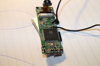
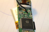
On fourth picture you can see buttons in top right corner of picture.

You cant connect bluetooth module on this PCB, you need to control buttons externally.


Best regards,
Peter
 
allright thanks peter! i'll try to figure all that out! hoping not to break it ^^

have any idea where i can get a bleutooth machine that could do the job?
 

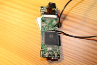
So i opened it up! it's exactly like you said, there are 2 button that look exactly like that!

I see that there are 4 metal lines coming from each corner of the buttons, i guess i have to attach my bluetooth reciever to all of them?

And when i press my bluetooth that the reciever closes the circuit and the machine think that i press the real button.

Is that how it should work in theory?

- - - Updated - - -

ok didnt see your message, thanks!
 

You can use wires as one option, just short wires, or you can use bluetooth solution posted in post #12.

Shorted wires are the same as when you press the button.


Best regards,
Peter
 
hey peter, i tried to do it with wires but i aint working.


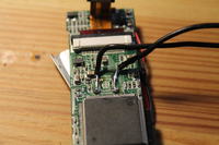
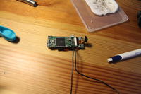
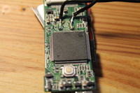
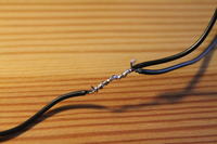
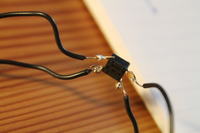
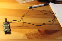
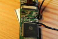
Any idea what i did wrong? its the first time i soldered something and i dont really have a good idea of what i'm doing,but i looked some things up and i think this is the correct way, any idea?
 

Check how you connect wires on contacts.

You wrongly solder wires.


img_15200.gif


Additional, this looks very scary :) but dont worry you will make something. Put smaller amount of soldering material, wires should be in contact with PCB only at switch contacts places. Pay attention on nearby capacitor.


Check with ohmmeter what contacts button connects when pressed.


Best regards,
Peter
 
oh ok! so i need to change the wires on the motherboard, from vertical to horizontal and then it should work?

Thanks peter!

- - - Updated - - -

hi peter, i tried to do what you said.
But now the device wont turn on.

The button at the button is to turn the device on. the one i'm working on is take a picture.

Any idea?

Thanks

- - - Updated - - -

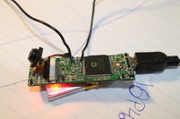
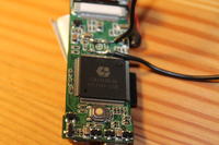
Allright tried some things out. whe i connect them both horizontally it doenst work,
but when i remove one, like on the picture it works, but i obviously cant take a picture
 

In post #18 illustration in bottom right corner on picture, one wire should be conected on 1 or 2 pins, and second wire should be connected on 3 or 4 pins.

Check with ohm meter that taster what you remove from PCB. Check orientation and contacts of removed taster, check that is the same as pins on mentioned illustration.

Also check second taster what you add on wires, did you connect that taster correctly ?


For picture taster should be pressed once and for video hold taster 2 sec.


Be careful with these contacts on PCB.

Before any next step do what I mention earlier and check to be sure what pins you should connect with wires.


Best regards,
Peter
 
Status
Not open for further replies.

Similar threads

Part and Inventory Search

Welcome to EDABoard.com

Sponsor

Back
Top