Continue to Site

Welcome to EDAboard.com

Welcome to our site! EDAboard.com is an international Electronics Discussion Forum focused on EDA software, circuits, schematics, books, theory, papers, asic, pld, 8051, DSP, Network, RF, Analog Design, PCB, Service Manuals... and a whole lot more! To participate you need to register. Registration is free. Click here to register now.

Add Offset Voltage to The Voltage-to-Current Converter Output

Status
Not open for further replies.

uranyumx

Advanced Member level 4
Joined
Mar 5, 2011
Messages
102
Helped
1
Reputation
2
Reaction score
0
Trophy points
1,296
Activity points
2,092
Hi,

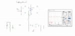
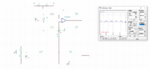
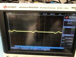
I have a voltage-to-current converter and try to add a DC offset voltage to voltage on the load at the output of the converter. The supply voltage of the opamp +/-5V and there is a 2kOhm load for verification of the converter output. The conversion output is matching with my calculation (Iout=Vin/25k). The problem is that offset voltage which is not added to the voltage on the load. I expect to measure a positive shifted signal from the buffer output. I have attached my design and measurement with the attached file.

Note: I placed the 4MOhm resistor to not lose the current output of the converter.

Thank you,
 

Attachments

  • Offset Problem.pdf
    674.1 KB · Views: 79

R4 in my schematic is your load ?

Note I get an offset current as you can see when Vin is 0

1605038033988.png


Regards, Dana.
 

Thank you @danadakk !

No, the load is not representing in the schematic but it is connected to the "3". When I simulate with TINA, I also see the offset voltage but I couldn't measure on my PCB.
 

What freq is your Vin at ?

Regards, Dana.
 

How do you add an offset voltage to a current source output? You can add an offset current, but not a voltage. The output voltage of a current source is set by output current multiply load resistance. However I don't recognize a load resistance in your circuit, I presume it's not the 4.7M resistor?
 

The load resistor is 2kOhm and connected to the line "3". Yes, the output is current, but there is a voltage drop on the resistor. So I want to add the offset voltage on the load resistor voltage.
 

You can either shift the footpoint of the "hidden" resistor or add a current source. What's the purpose of the series capacitor C72?
 

What does it mean footpoint? The capacitor will block DC signals.
 

Footpoint is the other terminal of the load resistor, e.g. ground. Too bad you don't show the circuit. DC signal at the current source output would only occur if it's intentionally or inadvertently fed to the input.
 

I guess the problem is related to the load type. When I played with the simulation file in TINA, I observed the shifting with an RC load. I have attached the simulation results of both a resistor and the RC load. But I didn't understand why it happens like this. Do you have an idea?

I have another question. I want to verify the current conversion outputs so I connected 2kOhm resistor at the output of the converter. When I feed +/- 1.5V voltage signals to the converter, I calculate to get Iout=1.5/25kOhm=60uA so I expect to measure V=60uA*2kOhm=+/-120mV across the resistor. But I measure +/-75mV across the 2kOhm resistor with an oscilloscope. Why is there a difference?
 

Attachments

  • RC Load.PNG
    RC Load.PNG
    51.6 KB · Views: 60
  • Resistor (2kOhm) Only Test.PNG
    Resistor (2kOhm) Only Test.PNG
    48 KB · Views: 85

Hi,
When I played with the simulation file in TINA, I observed the shifting with an RC load. I have attached the simulation results of both a resistor and the RC load. But I didn't understand why it happens like this. Do you have an idea?

You changed the resistors. That´s the reason why the DC level shifts.

But I measure +/-75mV across the 2kOhm resistor with an oscilloscope. Why is there a difference?
show the exact schematic with exact part values and the applied voltages, that you used to do the measurement.

Klaus
 

You changed the resistors
. You mean the increasing resistor value such as in MOhm level makes the shift visible? Why?

I have attached the input voltage signal and the voltage signal that was measured across the 2kOhm resistor. The input signal looks balanced but there is 0.05V difference. Input signal positive pahse is 1.15V, and the negative phase is 1.2V. The values and the exact schematic is in the first post. All the resistors (10k; 2k; 25k; 5k) have 0.1% tolerance and 1/20W.
 

Attachments

  • IMG_7868.jpg
    IMG_7868.jpg
    1.8 MB · Views: 51
  • IMG_7867.jpg
    IMG_7867.jpg
    1.9 MB · Views: 52

Status
Not open for further replies.

Similar threads

Part and Inventory Search

Welcome to EDABoard.com

Sponsor

Back
Top