Continue to Site

Welcome to EDAboard.com

Welcome to our site! EDAboard.com is an international Electronics Discussion Forum focused on EDA software, circuits, schematics, books, theory, papers, asic, pld, 8051, DSP, Network, RF, Analog Design, PCB, Service Manuals... and a whole lot more! To participate you need to register. Registration is free. Click here to register now.

ADC with pic-not able to get desired output

Status
Not open for further replies.
Your code should be something like this.

Code:
ADCON0bits.GO = 1;
while(ADCON0bits.GO);
ADCON0bits.ADON = 0;

Can you post yout hex and cof files? Check my last post it is updated.

Yes , The MCLR is pulled up with a resistor with Vcc.

- - - Updated - - -

Waseem is right. What is the duration of each interrupt caused due to timer?

Am new to programming controllers.. How to check that?? I just know that when the interrupt comes,it goes to the routine,but how to find out the duration of the interrupt?I will try what waseem has said.. Will come with the results within some time...
 

Attachments

  • pic18_try.zip
    2.1 KB · Views: 34

.cof file is not loading. It is showing empty. Can you code such that ADRESH is assigned to PORTD and send me the hex and .cof files?

Check this link for Timers http://extremeelectronics.co.in/mi...-pic18s-timers-pic-microcontroller-tutorial/

If you need a 10ms timer0 interrupt at Fosc = 20 MHz then you have to use the below code.

Code:
//Timer0
//Prescaler 1:1; TMR0 Preload = 15535; Actual Interrupt Time : 10 ms
 
//Place/Copy this part in declaration section
void InitTimer0(){
  T0CON	 = 0x88;
  TMR0H	 = 0x3C;
  TMR0L	 = 0xAF;
  GIE_bit	 = 1;
  TMR0IE_bit	 = 1;
}
 
void Interrupt(){
  if (TMR0IF_bit){ 
    TMR0IF_bit = 0;
    TMR0H	 = 0x3C;
    TMR0L	 = 0xAF;
    //Enter your code here
  }
}
 

I have it uploaded
 

Attachments

  • PIC_18try.zip
    2.5 KB · Views: 39

Compile the code I am sending and send me the hex and cof files.

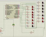
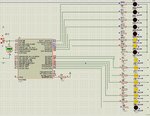
See the attached image. I am getting this value for your code and ADC I/P 2.5V

0x3FF = 1023d

1023d/2d = 511d = 0x1FF i.e., what you are getting for 2.5V (0-5v range) which is correct.
 

Attachments

  • chumma.txt
    541 bytes · Views: 45
  • adc op.jpg
    adc op.jpg
    317.4 KB · Views: 54
Last edited:

Compile the code I am sending and send me the hex and cof files.

See the attached image. I am getting this value for your code and ADC I/P 2.5V

Find attachment.
It must actually be FF on portd. I find it to be FE. Its not a matter.
Actually what was the mistake I made. I see no much difference in changes yu have made.. just a change in timer and its value. But what was the mistake I was making??

I will check it with my kit and will post here...
 

Attachments

  • PIC_18try.zip
    2.2 KB · Views: 34
Last edited:

See my last post. It's updated.I have used your code in the simulation. I will simulate it with my code and see and reply soon.

I checked with both the codes, yours and mine. I am getting 0x1FF or 511 for 2.5v and 0x3FF or 1023 for 5v which is right.

For 2.5v your ADRESH = 01111111 and ADRESL = 11000000

For 5v your ADRESH = 11111111 and ADRESL = 11000000

So your readings will be 0111111111 and 1111111111 {because you have chosen left justified)

So it is 0x1FF and 0x3FF
 
Last edited:

See my last post. It's updated.I have used your code in the simulation. I will simulate it with my code and see and reply soon.

I checked with both the codes, yours and mine. I am getting 0x1FF or 511 for 2.5v and 0x3FF or 1023 for 5v which is right.

For 2.5v your ADRESH = 01111111 and ADRESL = 11000000

For 5v your ADRESH = 11111111 and ADRESL = 11000000

SO your readings will be 0111111111 and 1111111111 {because you have chosen left justified)

So it is 0x1FF and 0x3FF

I will make it in my board and post sooner...
Regards
ram
 

I tried with this code and it is working fine.

Code:
#include<htc.h>

void interrupt isr(void);

void interrupt isr(void)
{
	if(TMR0IF) {
	TMR1IF = 0;
	ADCON0bits.GO = 1;
	while(ADCON0bits.GO);
	ADCON0bits.ADON = 0;
	PORTD = ADRESH;
	PORTC = ADRESL;
	TMR1H=0X3C;
    TMR1L=0XAF;
	}
}

void main()
{
	unsigned int result =0;
	
	TRISA  = 0XFF;
	TRISC  = 0x00;    
	TRISD  = 0X00;
	PORTD  = 0X00;   
	PORTA  = 0X00;
	PORTC  = 0x00;
	ADCON0 = 0x01;  
	ADCON1 = 0x0E; // Channel AN0 selected
	ADCON2 = 0X3E;   //Fosc/64 with time delay of 20*Tad
	T0CON  = 0X00;
	PEIE   = 0x01;  
	TMR0IE = 0x01;  
	GIE    = 0x01;
	TMR0H  = 0X3C;   
	TMR0L  = 0XAF;   
	TMR0IF = 0x00;
	TMR0ON = 0x01;
	
	while(1);	
}
 

Can you upload your proteus file as a zip here??
 

I got the output for the applied dc. But I do have an other problem . When I vary the pot , the digital output gets varies only for upto 2.5v of the applied input. After that , it remains as a constant at 1FF(corresponding value for 2.5v).Should I have to provide any external Vref to the controller. I have not given anything as of now , and I assume that it will by default take my Vref as 5v if nothing is connected externally. should I make any changes in my code. I have attached my code here for ease.
Code:
#include<htc.h>

void interrupt isr(void);

void interrupt isr(void)
{
	ADON = 1;
	ADRESH = 0X00;
	ADRESL = 0X00;
	ADFM = 1;
	TMR1ON = 0;
	if(TMR1IF) {
	TMR1IF = 0;
	ADCON0bits.GO = 1;
	while(ADIF == 0);
	ADCON0bits.ADON = 0;ADIF = 0;
	PORTD = ADRESH;
	PORTC = ADRESL;
	TMR1ON = 1;
	TMR1H=0XEF;
    TMR1L=0XFA;
	
	}
}

void main()
{
	unsigned int result =0;
	
	TRISA  = 0XFF;
	TRISC  = 0x00;    
	TRISD  = 0X00;
	PORTD  = 0X00;   
	PORTA  = 0X00;
	PORTC  = 0x00;
	ADCON0 = 0x00;  
	ADCON1 = 0x0E; // Channel AN0 selected
	ADCON2 = 0X3E;   //Fosc/64 with time delay of 20*Tad
	T1CON  = 0X00;
	PEIE   = 0x01;  
	TMR1IE = 0x01;  
	GIE    = 0x01;
	TMR1H  = 0XFF;   
	TMR1L  = 0XFA;   
	TMR1IF = 0x00;
	TMR1ON = 0x01;
	
	while(1);	
}

Regards
ram
 

Zip and post your proteus .dsn file. What value of Pot are you using?


The same zip file which you would be able to see some two threads before. I use the alike adc as of there module there. Anyway I have zipped it here too. I am using a 50k pot.

Regards
ram
 

Attachments

  • try.DSN.zip
    20.4 KB · Views: 36

The problem is in your code. Post your code and hex file Have you done the ADCON1 settings? Have you made the TRISC and TRISD as 0X00?
I have the code three threads back... I have made the settings.... Have a look please...(I am using a pic18f4550)
 

Can you send the hex file of your code? I used your .dsn file and my code. I am getting 0x1FF for 2.5v.

Maybe you compiled the code for 8MHz. Change the clock for mcu and set it to 8 MHz in Proteus. You will get the right value.
 

Attachments

  • sim ss 16.jpg
    sim ss 16.jpg
    261.5 KB · Views: 50
Last edited:

Can you send the hex file of your code? I used your .dsn file and my code. I am getting 0x1FF for 2.5v.

Maybe you compiled the code for 8MHz. Change the clock for mcu and set it to 8 MHz in Proteus. You will get the right value.

No No.. i am getting in proteus.. The same hex file , if i load in my board , its making the prob which i told before. I use a 20Mhz oscillator on my board with a pickit3 debugger. My adres value changes for values from 000 to 1FF when i change the pot dynamically. But remains at 1FF after 2.5v.....
 

oh!! I din do that...I will do it and post here
 

Status
Not open for further replies.

Similar threads

Part and Inventory Search

Welcome to EDABoard.com

Sponsor

Back
Top