Continue to Site

Welcome to EDAboard.com

Welcome to our site! EDAboard.com is an international Electronics Discussion Forum focused on EDA software, circuits, schematics, books, theory, papers, asic, pld, 8051, DSP, Network, RF, Analog Design, PCB, Service Manuals... and a whole lot more! To participate you need to register. Registration is free. Click here to register now.

ADC which has only vin and vref as inputs - problem

Status
Not open for further replies.

Monady

Advanced Member level 4
Joined
Dec 1, 2008
Messages
109
Helped
12
Reputation
24
Reaction score
3
Trophy points
1,298
Activity points
2,151
ADC Problem

Hi dear all friends,
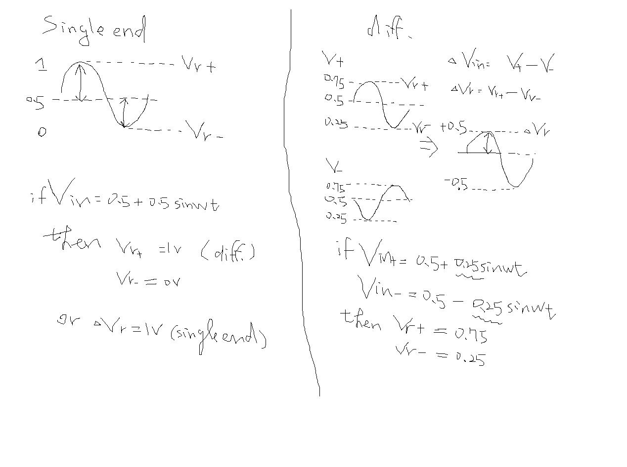
i had designed an ADC that had Only Vin and Vref as inputs. both of Vin and Vref were between 0V and 1V:
Vin=0.5+0.5*sin(ωt) & Vref=1
Now i have to use of fully differential inputs (Vin+, Vin- and Vref+, Vref-).
now i mixed up for determining values of Vref+ and Vref-.

in fully differential scheme we have:
Vin+=0.5+0.25sin(ωt) Vin-=0.5-0.25sin(ωt)

I would be appreciated for any suggestion.
 

Re: ADC Problem

Typical VREF+ and VREF- have some relation to the device ground so the formula should be


Vin+=VREF- + (VREF+ - VREF-)*(0.5+0.5*sin..)

Vin-= -0.5*sin..
 

    Monady

    Points: 2
    Helpful Answer Positive Rating
Re: ADC Problem

Hi.

A differential ADC has a positive (Vin+) and a negative (Vin+) analog input. These inputs require two equal drive signals that are 180° out of phase. The amplitude of each drive signal should equal the reference voltage, Vref, of the ADC to use the full dynamic range of the device. When a conversion occurs, the ADC converts only the difference between the two input signals on the Vin+ and Vin- pins. The ADC subtracts any portion of the signals that are in phase, such as noise, and these inphase signals thus disappear. The ADC adds the portion of the signals that is out of phase, which is the analog input. Thus, the amplitude of the converted signal is 2xVref.
The common-mode voltage, which you set up externally to the ADC, determines the value on which the differential analog inputs are centered. The reference level of the ADC determines the range of this
voltage. When an analog-to-digital conversion occurs, the ADC rejects this common-mode voltage.

(excerpt from EDN, June 12 2003, page 72)


So, you only have one Vref, that you set to Vref = 0.5 (in your example).

Arthur
 

ADC Problem

Dear Arthur, Thx for reply.
I' m not agree with you. As i saw previously in some thesis (e.g Flash ADC), all of comparators have 4 inputs (Vin+,Vin-,Vref+,Vref-) thus in this case i think differentially reference voltage using is unavoidable. i think if we use of single input merely, reference voltage can be single ended too.
 

ADC Problem

Thx for your reply and useful advice.
I would be appreciated if you give me reference of mentioned formula. besides for Vin-, we have this relation:

Vin-=VREF- + (VREF+ - VREF-)*(0.5-0.5*sin..)

is it true?
if you could please rewrite Vin+ or Vin- according to this formula of Vin+(because i think that you wrote 0.5 instead of 0.25):
Vin+=A(b)+A(in)Sin(ωt)

Thx in advance
 

ADC Problem

Hi Monady,

I drawn a simple figure for u to clarify it.
Please ref it.


Re: ADC Problem

Dear BrianSu, Thx very much.
But I'm not agree with you, because:
1)in the single ended topology, 0<Vin<1 thus Vref must change between 0 and 1 in order to covering all changes of Vin. but in differential topology,
Vin=Vin+ - Vin- , it means that Vin in diff topology changes between 0 and 1 yet. Thus in this case, Vref must cover all of Vin changes too.
in your relations, Vref=Vref+ - Vref- covers only half of input changes.

2)besides in ADCs, always Vref (single or diff) must be selected according to the domain of input changes, it means that in my case, Δ(Vref) muse be equal to one.

Correct me if i made a mistake plz.
Thx in advance.
 

Status
Not open for further replies.

Part and Inventory Search

Welcome to EDABoard.com

Sponsor

Back
Top