Continue to Site

Welcome to EDAboard.com

Welcome to our site! EDAboard.com is an international Electronics Discussion Forum focused on EDA software, circuits, schematics, books, theory, papers, asic, pld, 8051, DSP, Network, RF, Analog Design, PCB, Service Manuals... and a whole lot more! To participate you need to register. Registration is free. Click here to register now.

[SOLVED] ADC conversion problem- PIC16F877A

Status
Not open for further replies.

alekvodnjan

Junior Member level 2
Joined
Jun 19, 2012
Messages
22
Helped
0
Reputation
0
Reaction score
0
Trophy points
1,281
Activity points
1,516
Hello guys!
I need one advice. I'll be very very thankfull if you have it :-D

I'm doing ADC with PIC16F877A of an AC signal that is comming from inductive proximity sensor.

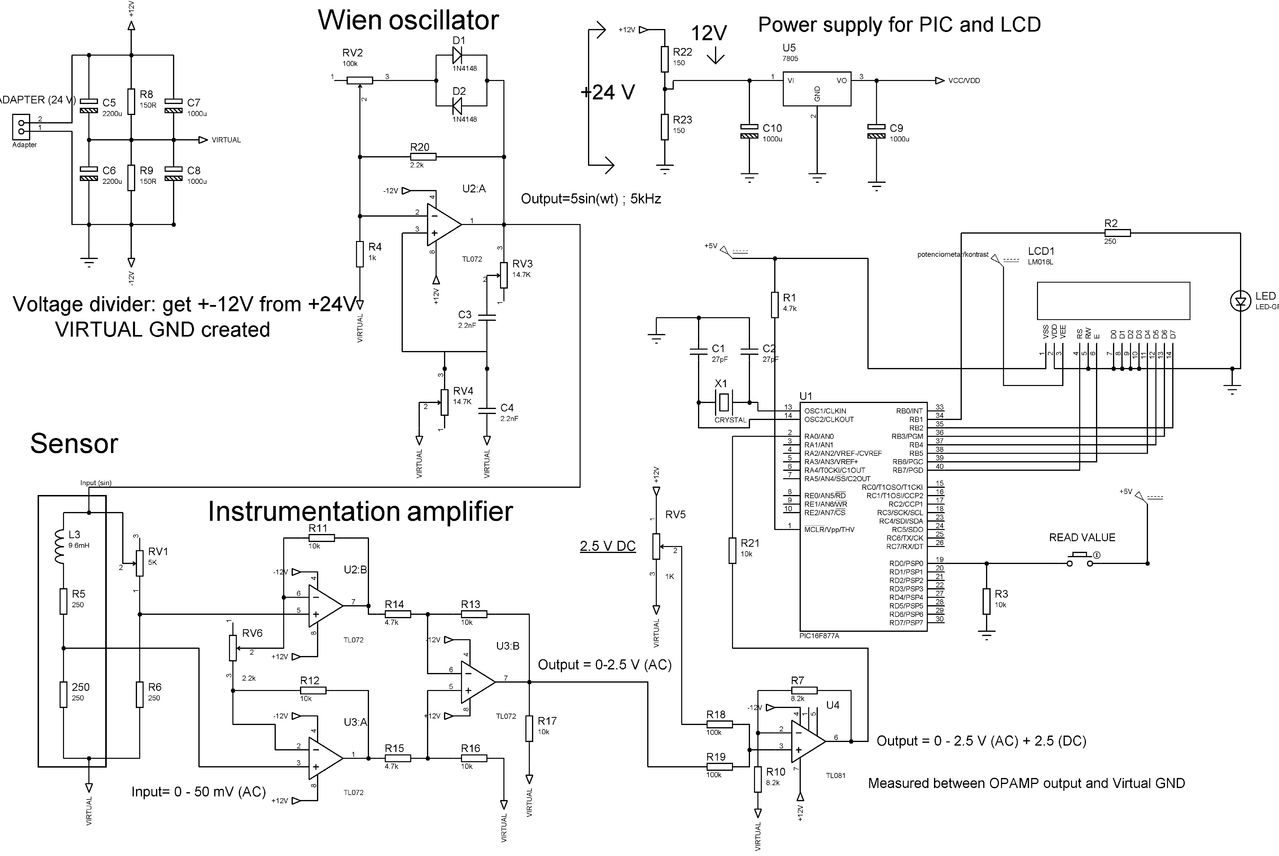
-First of all I have made an voltage divider to get +-12 V DC from 24 V DC adapter (needed for supplying OPAmps).

-With Wien oscillator I have got an AC signal with peak amplitude 5 V and frequency 5kHz (needed for supplying inductive sensor).

-Then with second half of Wheatstone bridge I get ballance between sensor and that bridge. Now I have differential AC voltage that goes from 0-50 mV.

-I have amplified this voltage 50 times with instrumentation amplifier. Now I have voltage changing from 0 to 2.5 V AC.

-With summing amplifier I added 2.5 V DC because microcontroler can't measure negative voltage. Signal of 2.5 V AC now swings around 2.5 V DC. Minimum peak of amplitude is 0 V and maximum 5 V. This is perfect because PIC's ADC is doing conversion between 0 and 5 V. I'm only interested in max amplitude so I made program in mikroC that's doing that. Max amplitude is changing between 2.5 and 5 V and I'm reading this change. Works very well in Proteus simulation.

Conclusion: I have an 0-2.5 V AC signal with 2.5 DC offset that now must go to PIC's ADC.


I have made a real circuit and measured values with oscilloscope and everything works fine. At the end of summing OP amp I get voltage that I want (I have measured this before connecting to PIC).

Here is schematic:
**broken link removed**

But the problem begins when I connect output signal to PIC's ADC. When I measure input to PIC with multimeter I get only constant DC signal of -3.5 V that is not changing like before did and I don1t have changing AC signal! I move sensor but nothing happens.

Of course, I have measured this between Input and Virtual GND. Every time I start AD conversion with push button I also get, at the output to LCD, constant value that is not changing.

Now I'm thinking. PIC is doing coversion between Vcc that is 5 V and GND. But my input signal is between opamp output and VIRTUAL GND!

I tried to simulate this in Proteus and I was right ('till now I've always simulated everything attached to GND and not to Virtual GND). I can't do ADC if my signal that I'm bringing to PIC is tied to VIRTUAL GND and PIC itself to GND. When I make connection in proteus between VIRTUAL GND and GND everything works fine.

But in real circuit I can't do that! One forum member told me that the main problem is that the virtual ground isn't designed to source or sink DC current. Loading it with the processor supply current would cause severe inbalance and this make sense.

What should I do now? How can I do ADC of an signal that is between output of my summing OP amp and VIRTUAL GND? Maybe I can add another circuit beetwen output and ADC that brings all to GND ? I really don't know so please help!!!

Thanks!

Alek Grabrović
 

Can you attach the schematic again Alek, for some reason the link is not working.

I think we need to see a schematic to answer your problem, from what you describe you did everything correctly and the two grounds are the problem. It may take some miinor redesigning to bring the real and virtual grounds together.

Brian.
 

Hey! Here is the link:

 
Last edited by a moderator:

I forgot to mention.
In my real circuit I didn't put R17 resistor (schematic) and value of R21 is 270 Ohm not 10k.
 

That's good, 10K would have been too high to satisfy the ADC input current requirement.

Your assumption about the difference in ADC ground and measurment ground is correct, in fact there is approximately 12V difference between them so it's no wonder the ADC reading is wrong.

There are several ways it can be fixed, I think the most practical way is to move the PIC and LCD ground connections to the virtual ground. I would also add a pair of reverse biased diodes across the ADC input at the PIC pin, one to VSS and one to VDD to limit over voltage or reverse polarity which could permanently damage the device. The drawback to simply moving the ground connections is the current from each side of the virtual ground circuit will be different and the center point potential will shift. I would replace R8 and R8 with an active voltage divider to overcome that. There are purpose made ICs to provide a precision split supply but as the current is relatively small you might be able to utilize an op-amp,maybe with a pair of small transistors to do the same job. All you need is a potential divider (say 2 x 10K resistors) across the input voltage and a unity gain buffer at their junction to ensure unbalanced loads on each half do not shift the virtual ground potential.

If you are using a backlight on the LCD, it is isolated from all the other pins so connect it directly across the incoming supply, using suitable current limiting if necessary, rather than from one half of the split supply.

Brian.
 
What should I do now? How can I do ADC of an signal that is between output of my summing OP amp and VIRTUAL GND? Maybe I can add another circuit beetwen output and ADC that brings all to GND ? I really don't know so please help!!!

I think scaling the inputs to the summing OPAMP before ADC to the actual ground (0V) would solve this problem. Instead of using Virtual Ground for DC bias in summing opamp, use actual GND (0V) and adjust the DC bias so that the output will be between 0 to 5V. For this you have to use single supply opamp.
 
I think scaling the inputs to the summing OPAMP before ADC to the actual ground (0V) would solve this problem. Instead of using Virtual Ground for DC bias in summing opamp, use actual GND (0V) and adjust the DC bias so that the output will be between 0 to 5V. For this you have to use single supply opamp.

Thanks ravindragudi for answer. Can you suggest me what single supply OP-amp is best to use for this purpose? Maybe one from TL0XX or LMXXX series because we only have those one in our local store.

Brian I really apprecciate your detailed explanation.
Voltage for LCD backlight is comming from RBO port of PIC that is always on.

I'll draw schematic with your suggested corrections and post it here later so that you can see if I did understand everything well.

Thanks a lot guys!
If you have anything else in mind fell free to comment.

- - - Updated - - -

That's good, 10K would have been too high to satisfy the ADC input current requirement.

Your assumption about the difference in ADC ground and measurment ground is correct, in fact there is approximately 12V difference between them so it's no wonder the ADC reading is wrong.

There are several ways it can be fixed, I think the most practical way is to move the PIC and LCD ground connections to the virtual ground. I would also add a pair of reverse biased diodes across the ADC input at the PIC pin, one to VSS and one to VDD to limit over voltage or reverse polarity which could permanently damage the device. The drawback to simply moving the ground connections is the current from each side of the virtual ground circuit will be different and the center point potential will shift. I would replace R8 and R8 with an active voltage divider to overcome that. There are purpose made ICs to provide a precision split supply but as the current is relatively small you might be able to utilize an op-amp,maybe with a pair of small transistors to do the same job. All you need is a potential divider (say 2 x 10K resistors) across the input voltage and a unity gain buffer at their junction to ensure unbalanced loads on each half do not shift the virtual ground potential.

If you are using a backlight on the LCD, it is isolated from all the other pins so connect it directly across the incoming supply, using suitable current limiting if necessary, rather than from one half of the split supply.

Brian.

Here are modifications I did (marked with blue circle). I only don't know how to solve active voltage divider you mentioned (language difficulties so I'm not sure what exactly to do). Can you please draw schematic of that part or just reffer me to some post on this forum where I can find out how to do it?

popravljeno.jpg

Also I have another question. If I put diodes on ADC wouldn't that affect measuring? I have voltage drop of 0.7 V and diodes are non-linear and I need linear measuring? I'm courius about that.

Do you think ravindragudi's method is more acceptable ?
 

Ravindragudi's idea should work but you misunderstood what I meant about the diodes for protecting the ADC. I have attached a diagram of what I proposed and two alternative diagrams for creating the virtual ground. If you use the op-amp solution you need a type with high current output capability.

Brian.

protect001a.jpg
vg1001a.jpg
vg2002a.jpg
 
Oh thank you so much. Jeez I totally misunderstood what you told me about diodes. Now it makes absolute sense. :)

For voltage supply I think I'll go with second solution 'cause we don't have TLE2426 in our local store.

vg2002a.jpg

Also, I'll try method with opamp. I added 100nF capacitor to block DC. I think now I'll have AC signal swinging around 0 V (GND). I'll add 2.5 DC component with single supply opamp. Please check schematic and tell me if my values of capacitor and resistors are ok and if the opamp I have choosen is ok.

Correct my schematic if it's wrong. Would it be clever If I put one more 100nF caapacitor between R3 resistor and ground?

Here is schematic:
Primjer.png
 

I think the circuit you posted for opamp with single supply should work. I would suggest you to change the value of RV1 pot from 1k ohm to 10k ohm or more. Or else use precision resistors divider circuit with low temp co-efficient.
The LM358N has 7mV input offset voltage and 150nA input offset current - looks high. But if your application doesn't need much of accuracy and if the error introduced by this opamp is okay - then no issues.
Also selection of the R1 (270 ohm) resistor depends upon the sensor characteristics - it can be experimented and selected i guess.
 
I see. Hmm I'll rather take another LM opamp that has better characteristics. But I don't know which one and what to look for. This choice was my lucky guess.

Do you have in mind any TL or LM series opamp that is good enough for this application (low input offset and current, and as Brian have suggested high current output capability)? I'm bounded only to this series of opamps 'cause these are the only one I could get in local store. Ordering it from outside will take too much time.

One more question. Due to experimentation in real circuit I did with PIC while connected to different ground than input to ADC, is there any chance I accidently damaged PIC? I mean, PIC didn't get hot or anything. He was giving me output to LCD all the time. But maybe I damaged only ADC without knowing, and next time it will give me wrong results due to that. I would have know if all PIC is permanently damaged. It would just not work and I'll be getting blank screen on LCD.
But is there any chance that I damaged only ADC input? I don't know if it is possible to damage only parts of microcontroller?

I would like to precede all problems that can affect my measurement. I don't want later on to ask myself is that because of that or that.
 

Definitely you have to take precaution when you are experimenting ... But if you are using the clamp diodes as suggested by Brian, then its safe. Also in the beginning measure the voltage at R21 (10k ohm) pad. Remove this resistor to safeguard the PIC. Once you are sure of the voltage level you can assemble back the R21 resistor.

I will try to figure out some opamp for you and let you know. But for initial experimentation the one you are having now should be ok.
 

Ravindragudi's advice about disconnecting the feed t the ADC is good. You can measure the voltage with a meter until you are sure it is safe to reconnect it. The ADC input is protected by internal clamp diodes which are not as robust as the ones you added outside but they do give a reasonable degree of protection. The only way to be sure if the ADC survived is to see if it gives the right output!

I still have some concerns about the uneven loading on the + and - split around the virtual ground. Ideally, I you should try to balance the load equally on them but all the PIC and LCD circuitry sits only on one side. The LCD backlight is probably to highest current sink so if possible, I would try to power it from the 24V input rather than 5V stepped down from 12V, it will require a transistor driver and a few resistors to get the biasing to work due to the voltage offset.

It occured to me that there is another way to produce the split supply which overcomes the current capability problem although it would only work if you could either increase the 24V to 27V or run the circuit on a lower voltage. Simply stack two 7812 regulators one on top of the other and take the ground output from their junction. If you can live with a lower supply voltage, use two 7810 or 7809 regulators which would let you keep the 24V input.

Brian.
 

Ok. Only that is important is that I get right mesurement on LCD. For now, backlight is not so important to me. It can be without it if you ask me. Later on, I'll deal with that.

Second, here is schematic of what you have said to me:

regulatori.jpg

Correct it if I have done something wrong.

- - - Updated - - -

Also, I have changed opamp method just little bit. 'Cause I'm using non-inverting opamp I think it should be like this:
sumator.jpg
 

Now I have noticed one mistake I made. First schematic should be without resistors (LM7810 one). I think it would be clever if I also put an heat sink on both 7810.
I don't know if I should put one more capacitor at 24 V input like you did on your two above schematics..
 

The regulators are not quite as I intended. I can't produce drawings easily at the moment so I will have to describe it:

1. wire one capacitor across the incoming 24V.
2. join both 7810 inputs together and to the +24V input.
3. Connect one of the 7810 ground pins to the negative side of the incoming 24V. This will give you a regulated 10V at it's output.
4. Connect the other 7810 ground pin to the output of the first 7810. This will also regulate 10V but it will be above the other regulator output giving 20V.
5. Take your +10V supply from the second 7810, virtual ground from the output of the first 7810 and -10V from the ground of the first 7810.

It would be like stacking one 10V regulator on top of the other and taking virtual ground from their mid point. Be sure to add capacitors (~1uF) across the input and ground pin and the output and ground pin of each regulator and keep them as close as possible to the regulator body.

Brian.
 

Here it is. I think I connected exactly as you explained to me, but according to simulation I'm getting strange results:
Regulators.png
 

That is what I explained. For it to work you need current to be drawn through the regulators. Although it is capable of more current, it suffers the drawback that 78xx series regulators can't sink current.

How stable is your incoming 24V? If it is already regulated, you might be able to create a virtual ground by using a single 12V regulator and using it's output as the ground point although this still suffers from inability to sink current.

It occurred to me that the current drawn by the op-amps is very small and it may be easier to use a single 7812 regulator to produce +12V and an independent electronic -12V generator. Does this sound feasible to you? I am thinking of something like an MC34063A running from the 24V input and configured to give a regulated -12V out. That method, although slightly more complicated, does have the advantage of high current capability on the +12V output which you can further regulate down to 5V for he PIC/LCD.

Brian.
 

For experimentation I use 24 V DC generator. I think that it's not quite stable 'cause every time, when I power it on although it is alredy adjusted to 24 V, I have to slightly adjust Wien oscillator to get exactly 5 volts.
At the end I'll use 24 V AC/DC adapter that is regulated and i think quite stable.

As I can see, I can get MC34063A from a local dealer. I have never worked with it so I don't know how to appropriate connect it to get this -12 V.

What are the consequences of non capability of 78xx regulators to sink current? Would this method work in my circuit regardless to that?

You gave me few solutions to my problem. My first thought was to use circuit with opamp at junction of two resistors.
Can I stick with that method or should I consider other solutions you gave to me because method with opamp might not work?

- - - Updated - - -

I would like to finally take the easiest, cheapest and of course fastest method. I can't get all elements until Monday. Then I'll be able to test finally method I have choosen.
So it would be awesome if I can stick to one solution 'cause sensor is not mine and, due to that, every time I have to go to laboratory to get sensor and do the testing. Problem is that I cannot use this laboratory every time and how much I want. My time for testing is really limited
 
Last edited:

The MC34063A is a cheap and stable, it can be configured to give regulated step up or step down voltages and with either output polarity. You could use one for the +12V supply as well as it will dissipate less heat than a linear regulator.

The most precise mid-voltage will come from an op-amp splitter but you need one which can supply enough output current and at the same time be stable while driving a capacitive load. The resistor in series with the output pin in the schematic is to isolate it from the direct connection to capacitors on the + and - supply halves but as it appears in series with the virtual ground output it also limits the current you can pass through it. There are many high current 'buffer amplifiers' you can use, they are basically unity gain power amplifiers that are happy to drive capacitive loads, they do not need isolating resistors but they are considerably more expensive.

The sink problem with 78xx regulators is not obvious at first. When enough current flows through them the circuit will work fine but if you imbalance the load between outputs, the virual ground will try to shift voltage. While an op-amp can swing it's output up or down so it provides or draws current, a regulator can only source current and if the imbalance pulls the virtual gound voltage higher than the regulator output, there is nothing it can do to compensate, it simply thinks there is enough voltage at it's output already and stops conducting.

Brian.
 

Status
Not open for further replies.

Similar threads

Part and Inventory Search

Welcome to EDABoard.com

Sponsor

Back
Top