Continue to Site

Welcome to EDAboard.com

Welcome to our site! EDAboard.com is an international Electronics Discussion Forum focused on EDA software, circuits, schematics, books, theory, papers, asic, pld, 8051, DSP, Network, RF, Analog Design, PCB, Service Manuals... and a whole lot more! To participate you need to register. Registration is free. Click here to register now.

adc configuration and conditional statement using micro c

Status
Not open for further replies.

glenndingding

Newbie level 5
Joined
Feb 15, 2012
Messages
10
Helped
0
Reputation
0
Reaction score
0
Trophy points
1,281
Location
Philippines
Activity points
1,403
hi everyone,

i am using MICRO C for my PIC16f877a micro controller but i have a problem encountered regarding the adc configuration and and making conditions in comparing constants.

i have 3 inputs which in need to be read in adc.....

1st input ...the adc read it. then it compares to a constant value of 12. then it gives 2 outputs. first output is switch relay and second output led blink.
2nd input ...the adc read it. then it compares to a constant value of 16. then it gives 2 outputs. first output is switch relay and second output led blink.
3rd input ...the adc read it. then it compares to a constant value of 24. then it gives 2 outputs. first output is switch relay and second output led blink.

here is my code .....please help me to correct..


Code:
void ADCInit(){         //configuring adc module
}
unsigned int ADCRead(){

ADCON1 = 0xFF;          //configuring AN0-AN7 as analog inputs and  VREF
ADCON0   = 0x07;        //configuring  analog channels  AN0, AN1, AN2
ADON_BIT     = 1;       //switch on adc module
GO_DONE_BIT   =1 ;      //start conversion

while(GO_DONE_BIT);      //wait for the condition to finish
ADON_BIT= 0;            //switch off adc
}

void main(){

ADCInit();                 //initializes adc in the main program

TRISB = 0x00;
PORTB = 0x00;              //putting port B as output   for LED indicator
TRISD = 0X00;
PORTD = 0x00;              //putting port D as output for relay switching


while(1){
unsigned int sensor1_15A;   //assigning variable for input1
unsigned int sensor2_20A;   //assigning variable for input2
unsigned int sensor3_30A;   //assigning variable for input3

unsigned int reading1;      //assigning variable for adc reading1 for input1
unsigned int reading2;      //assigning variable for adc reading2 for input2
unsigned int reading3;      //assigning variable for adc reading3 for input3

reading1 = sensor1_15A-511*0.012207;    //assigning variables with constants
reading2 = sensor2_20A-511*0.012207;    //assigning variables with constants
reading3 = sensor3_30A-511*0.012207;    //assigning variables with constants


sensor1_15A = ADCRead(1);      //the adc reading of input 1 will be placed in the first variable sensor1_15A
sensor2_20A = ADCRead(2);      //the adc reading of input 2 will be placed in the first variable sensor2_20A
sensor3_30A = ADCRead(3);      //the adc reading of input 3 will be placed in the first variable sensor3_30A


while(1){
    if (reading1>12){       // condition when the (adc reading-511*0.012207) is greater to the set value of 12 amperes
                            //adc reading-511*0.012207 = amperes.......
		PORTD.6 = 0xFF;      //port D is used fOr switching relay1  at RD6 at pin 29 of PIC16f877a is set to input for relay switching
                                     // I do not know if it is PORTD.6..  i consider RD0, RD1, RD2, RD3, RD4, RD5,RD6, RD7 = pin 0,1,2,3,4,5,6,7
		PORTD.6 = 0x00;
		delay_ms(5000);     //port D at at RD6 at pin 29 of PIC16f877a is set to output for relay switching

		PORTB.7 = 0x00;      //PORT B AT rb7 at pin 40 of pic16f877a is set to output for led blinking
		delay_ms(1000);
		PORTB.7 = 0xFF;      //PORT B AT rb7 at pin 40 of pic16f877a is set to input for led blinking
		delay_ms(1000);
	else
		PORTD.6 = 0xFF;      //PORT D AT  RD6 is nothing to do
		PORTB.6 = 0x00;      //PORT B AT rb6 at pin 39 of pic16f877a is set to output for led steady light
	}

	if (reading2>16){          // condition when the (adc reading-511*0.012207) is greater to the set value of 16 amperes
                                    //adc reading-511*0.012207 = amperes.......
		PORTD.5 = 0xFF;     //port D is used fpr switching relay2  at RD5 at pin 28 of PIC16f877a is set to input for relay switching
                                     // I do not know if it is PORTD.5..  i consider RD0, RD1, RD2, RD3, RD4, RD5,RD6, RD7 = pin 0,1,2,3,4,5,6,7
		delay_ms(5000);
		PORTD.5 = 0x00;
		delay_ms(5000);
		
		PORTB.5 = 0x00;      //PORT B AT rb5 at pin 38 of pic16f877a is set to output for led blinking
		delay_ms(1000);
		PORTB.5 = 0xFF;     //PORT B AT rb5 at pin 38 of pic16f877a is set to input for led blinking
		delay_ms(1000);
	else
		PORTD.5 = 0xFF;      //PORT D AT  RD5 is nothing to do
		PORTB.4 = 0x00;     //PORT B AT rb4 at pin 37 of pic16f877a is set to output for led steady light
	}

	if (reading3>24){            // condition when the (adc reading-511*0.012207) is greater to the set value of 16 amperes
                                    //adc reading-511*0.012207 = amperes.......
		PORTD.4 = 0xFF;     //port D is used fpr switching relay3  at RD4 at pin 28 of PIC16f877a is set to input for relay switching
                                     // I do not know if it is PORTD.5..  i consider RD0, RD1, RD2, RD3, RD4, RD5,RD6, RD7 = pin 0,1,2,3,4,5,6,7
		delay_ms(5000);
		PORTD.4 = 0X00;
		delay_ms(5000);
		
		PORTB.3 = 0x00;       //PORT B AT rb3 at pin 36 of pic16f877a is set to output for led blinking
		delay_ms(1000);
		PORTB.3 = 0xFF;      //PORT B AT rb3 at pin 36 of pic16f877a is set to output for led blinking
		delay_ms(1000);
	else
		PORTD.4 = 0xFF;      //PORT D AT  RD4 is nothing to do
		PORTB.2 = 0x00;      //PORT B AT rb2 at pin 35 of pic16f877a is set to output for led steady light
	}
}

}
}

MODERATOR NOTE - USE CODE TAGS

..............the problems occur:
1. line 38 , 39, 40 .......too many parameters
2. line 46, .......;expected, but '6' found
3. line 46, .......'{' expected, but ';' found
4. line 95..........specifier needed
5. line 95........invalid declarator expected '(' or identifier
6. line 95.......internal error"


please help me to correct the configuration and the errors please
 

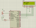
Lets have a look on small code..
Configuration of ADC can be seen on DATASHEET Page 129 and 130

Code:
// LCD module connections
sbit LCD_RS at RC0_bit;
sbit LCD_RW at RC1_bit;
sbit LCD_EN at RC2_bit;
sbit LCD_D4 at RB4_bit;
sbit LCD_D5 at RB5_bit;
sbit LCD_D6 at RB6_bit;
sbit LCD_D7 at RB7_bit;

sbit LCD_RS_Direction at TRISC0_bit;
sbit LCD_EN_Direction at TRISC2_bit;
sbit LCD_D4_Direction at TRISB4_bit;
sbit LCD_D5_Direction at TRISB5_bit;
sbit LCD_D6_Direction at TRISB6_bit;
sbit LCD_D7_Direction at TRISB7_bit;
// End LCD module connections


unsigned int temp_data;
unsigned char adc_data[16];
void main()
{
 //Configuring all as  Analog Channels and Display Data on Channel-0 on LCD
 //Data Displayed on LCD is as it is.
 //No Conversion Occurs
 ADCON0 = 0x81;
 ADCON1 = 0xC0;      //Made all channel as analog channels
 Lcd_Init();
 Delay_ms(100);
 LCD_RW = 0;
 Lcd_Cmd(_LCD_CLEAR);
 Lcd_Cmd(_LCD_CURSOR_OFF);
 ADC_Init();
 Delay_ms(100);
 while(1)
 {
  Lcd_Cmd(_LCD_CLEAR);
  Lcd_Out(1,1,"ADC DATA");
  temp_data = ADC_Read(0);
  IntToStr(temp_data,adc_data);
  Lcd_Out(2,1,adc_data);
  Delay_ms(1000);
 }
}

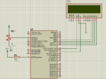
Capture.PNG

Here is the Result of Simulation
Working Fine
Capture.PNG

Hope this help
 

It is difficult to track down the errors without the line numbers and complete code, but

Code:
if(...) {

else

}

should be

Code:
if(...){

}
else {


}

Keith

---------- Post added at 17:54 ---------- Previous post was at 17:52 ----------

Also, you have two while(1) statements, one inside the other. It will never get out of the inner one, so the first one isn't required.

Keith.

---------- Post added at 17:57 ---------- Previous post was at 17:54 ----------

PS

You seem to assign values to "reading1/2/3" based on "sensor1_15A" etc but those variables have no value at the time you do that.
 

I haven't looked at your methodology for what your trying to do but I have tidied up you code a little bit:

Code:
void ADCInit(){         //configuring adc module
}
unsigned int ADCRead(){

ADCON1 = 0xFF;          //configuring AN0-AN7 as analog inputs and  VREF
ADCON0   = 0x07;        //configuring  analog channels  AN0, AN1, AN2
ADON_BIT     = 1;       //switch on adc module
GO_DONE_BIT   =1 ;      //start conversion

while(GO_DONE_BIT);      //wait for the condition to finish
ADON_BIT= 0;            //switch off adc
}

void main(){

	ADCInit();                 //initializes adc in the main program

	TRISB = 0x00;
	PORTB = 0x00;              //putting port B as output   for LED indicator
	TRISD = 0X00;
	PORTD = 0x00;              //putting port D as output for relay switching


	unsigned int sensor1_15A;   //assigning variable for input1
	unsigned int sensor2_20A;   //assigning variable for input2
	unsigned int sensor3_30A;   //assigning variable for input3

	unsigned int reading1;      //assigning variable for adc reading1 for input1
	unsigned int reading2;      //assigning variable for adc reading2 for input2
	unsigned int reading3;      //assigning variable for adc reading3 for input3

	reading1 = sensor1_15A-511*0.012207;    //assigning variables with constants
	reading2 = sensor2_20A-511*0.012207;    //assigning variables with constants
	reading3 = sensor3_30A-511*0.012207;    //assigning variables with constants


	sensor1_15A = ADCRead();      //the adc reading of input 1 will be placed in the first variable sensor1_15A
	sensor2_20A = ADCRead();      //the adc reading of input 2 will be placed in the first variable sensor2_20A - If you are going to place a variable into this function you need to say so on line 3 - like ASCRead(unsigned char val);
	sensor3_30A = ADCRead();      //the adc reading of input 3 will be placed in the first variable sensor3_30A


	while(1){
		if (reading1>12){       // condition when the (adc reading-511*0.012207) is greater to the set value of 12 amperes
								//adc reading-511*0.012207 = amperes.......
			PORTD.6 = 0xFF;      //port D is used fOr switching relay1  at RD6 at pin 29 of PIC16f877a is set to input for relay switching
										 // I do not know if it is PORTD.6..  i consider RD0, RD1, RD2, RD3, RD4, RD5,RD6, RD7 = pin 0,1,2,3,4,5,6,7
			PORTD.6 = 0x00;
			delay_ms(5000);     //port D at at RD6 at pin 29 of PIC16f877a is set to output for relay switching

			PORTB.7 = 0x00;      //PORT B AT rb7 at pin 40 of pic16f877a is set to output for led blinking
			delay_ms(1000);
			PORTB.7 = 0xFF;      //PORT B AT rb7 at pin 40 of pic16f877a is set to input for led blinking
			delay_ms(1000);
		}
		else	{
			PORTD.6 = 0xFF;      //PORT D AT  RD6 is nothing to do
			PORTB.6 = 0x00;      //PORT B AT rb6 at pin 39 of pic16f877a is set to output for led steady light
		}

		if (reading2>16){          // condition when the (adc reading-511*0.012207) is greater to the set value of 16 amperes
										//adc reading-511*0.012207 = amperes.......
			PORTD.5 = 0xFF;     //port D is used fpr switching relay2  at RD5 at pin 28 of PIC16f877a is set to input for relay switching
										 // I do not know if it is PORTD.5..  i consider RD0, RD1, RD2, RD3, RD4, RD5,RD6, RD7 = pin 0,1,2,3,4,5,6,7
			delay_ms(5000);
			PORTD.5 = 0x00;
			delay_ms(5000);
			
			PORTB.5 = 0x00;      //PORT B AT rb5 at pin 38 of pic16f877a is set to output for led blinking
			delay_ms(1000);
			PORTB.5 = 0xFF;     //PORT B AT rb5 at pin 38 of pic16f877a is set to input for led blinking
			delay_ms(1000);
		}
		else
			PORTD.5 = 0xFF;      //PORT D AT  RD5 is nothing to do
			PORTB.4 = 0x00;     //PORT B AT rb4 at pin 37 of pic16f877a is set to output for led steady light
		}

		if (reading3>24){            // condition when the (adc reading-511*0.012207) is greater to the set value of 16 amperes
										//adc reading-511*0.012207 = amperes.......
			PORTD.4 = 0xFF;     //port D is used fpr switching relay3  at RD4 at pin 28 of PIC16f877a is set to input for relay switching
										 // I do not know if it is PORTD.5..  i consider RD0, RD1, RD2, RD3, RD4, RD5,RD6, RD7 = pin 0,1,2,3,4,5,6,7
			delay_ms(5000);
			PORTD.4 = 0X00;
			delay_ms(5000);
			
			PORTB.3 = 0x00;       //PORT B AT rb3 at pin 36 of pic16f877a is set to output for led blinking
			delay_ms(1000);
			PORTB.3 = 0xFF;      //PORT B AT rb3 at pin 36 of pic16f877a is set to output for led blinking
			delay_ms(1000);
		}
		else	{
			PORTD.4 = 0xFF;      //PORT D AT  RD4 is nothing to do
			PORTB.2 = 0x00;      //PORT B AT rb2 at pin 35 of pic16f877a is set to output for led steady light
		}
	}
}

You need to set the ADC channel that you are taking the measurement from before you take that measurement otherwise you will always be reading the same channel, you cannot just say ADCRead(1);

Hope this helps.

/Pete
 

Status
Not open for further replies.

Part and Inventory Search

Welcome to EDABoard.com

Sponsor

Back
Top