Continue to Site

Welcome to EDAboard.com

Welcome to our site! EDAboard.com is an international Electronics Discussion Forum focused on EDA software, circuits, schematics, books, theory, papers, asic, pld, 8051, DSP, Network, RF, Analog Design, PCB, Service Manuals... and a whole lot more! To participate you need to register. Registration is free. Click here to register now.

AD8561 Comparator circuit problem

Status
Not open for further replies.

SAILLESH.SABARISH

Member level 1
Joined
Dec 15, 2009
Messages
32
Helped
0
Reputation
0
Reaction score
0
Trophy points
1,286
Location
india
Activity points
1,512
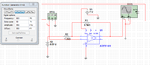
I want to have a simple comparator operation using AD8561 since my application needs faster operation.
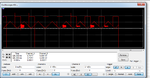
I tried with simulation and it was working . when i go for the implementation it doent work.
I want a operation like when the reference voltage goes below 400mv the out put should go high.
i will attach the circuit i am using . Pls correct me if i was wrong.
thanks in advance.
 

Attachments

  • file one.png
    file one.png
    27.8 KB · Views: 120
  • file two.png
    file two.png
    41.8 KB · Views: 108

The AD8561 has three supply pins: V+, V-, and GND. Did you connect them all appropriately? I ask because there's no GND connection in your schematic.
 

i have now grounded the 5th pin ...called the balance in the picture .and now every thing works well..
I think that will be the ground.
 

yes ..it is a latch pin and i cant make it work after some time....can you suggest me some solutions for this.....
 

You might be better off just building it. It is impossible to tell from your schematic if the pin order matches the model sub-circuit which would be where I suspect the problem is, given that the symbol is incorrect.

Keith
 

Status
Not open for further replies.

Similar threads

Part and Inventory Search

Welcome to EDABoard.com

Sponsor

Back
Top