Continue to Site

Welcome to EDAboard.com

Welcome to our site! EDAboard.com is an international Electronics Discussion Forum focused on EDA software, circuits, schematics, books, theory, papers, asic, pld, 8051, DSP, Network, RF, Analog Design, PCB, Service Manuals... and a whole lot more! To participate you need to register. Registration is free. Click here to register now.

AD8302 Phase detector IC

Status
Not open for further replies.

Qamar Shafi

Junior Member level 2
Joined
Jul 27, 2020
Messages
22
Helped
0
Reputation
0
Reaction score
1
Trophy points
3
Activity points
142
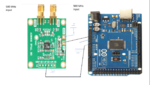
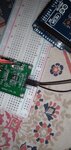
I am using AD 8302 For phase difference detection at 500 MHz .
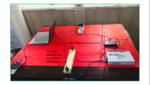
I have placed two antennas at 30 cm distance . The antennas are receiving and output at VPH is not stable.
How can I get a stable voltage and calibrate for phase difference detection. Signal level is 30 dBm as checked on spectrum analyzer.
 

Hi,

please show us your schematic as well as a sketch of your measurement setup. Otherwise it is impossible to give any advice.

BR
 

Hi,

please show us your schematic as well as a sketch of your measurement setup. Otherwise it is impossible to give any advice.

BR
--- Updated ---

Hi,

please show us your schematic as well as a sketch of your measurement setup. Otherwise it is impossible to give any advice.

BR
This is exactly my problem which I want to solve. I need to find phase difference between two helical antennas at 500MHz.
Thank you alot
 

Attachments

  • Screenshot (86).png
    Screenshot (86).png
    1.3 MB · Views: 218
  • Screenshot (87).png
    Screenshot (87).png
    1.1 MB · Views: 216

- In wich way are your measurement results are not stable?
- Which power is used by your transmitter?
- I see a lot of cables (on breadboard/USB) in direct sight of your TX antenna, which are picking up the RF signal (\[\lambda (\mathrm{500MHz}) = 0.6~m\])
 

- In wich way are your measurement results are not stable?
- Which power is used by your transmitter?
- I see a lot of cables (on breadboard/USB) in direct sight of your TX antenna, which are picking up the RF signal (\[\lambda (\mathrm{500MHz}) = 0.6~m\])
Should I shield them in an aluminum foil?
--- Updated ---

Should I shield them in an aluminum foil?
The output at VPH and GD is not stable. If I move the two antennas the voltage changes abruptly. I should get a constant voltage for corresponding phase difference.
 

Please elaborate what you mean by not stable. How do your MCU readings look like? How can your GD not be stable, according to your attached image it is your sytsem ground. How have you determined GD is not stable (referenced to which node)? How does your GD (AD8302 board) to GND (Arduino board) look like?
 

Should I shield them in an aluminum foil?
--- Updated ---


The output at VPH and GD is not stable. If I move the two antennas the voltage changes abruptly. I should get a constant voltage for corresponding phase difference.
If I donot turn on any RF source even then the output voltage os not constant.
What is the reason?
--- Updated ---

Please elaborate what you mean by not stable. How do your MCU readings look like? How can your GD not be stable, according to your attached image it is your sytsem ground. How have you determined GD is not stable (referenced to which node)? How does your GD (AD8302 board) to GND (Arduino board) look like?
The value goes from 0.91 to 1.02 even when I am not having any transmitter in vicinity.

And the I am measuring voltage between +VP and GD for phase difference.this value is fed to Analog to Digital Conversion (ADC) .
 

Attachments

  • IMG_20210216_232143.jpg
    IMG_20210216_232143.jpg
    2.9 MB · Views: 131
  • 16135000032902577554908852758395.jpg
    16135000032902577554908852758395.jpg
    2.5 MB · Views: 166
Last edited:

So I'm asking again, how are your measurement results look like? You are measuring a floating (AC-coupled) input. The ADC resolution of an arduino uno board has 10 Bit, which uses a 5 V reference. So your LSB is about 5 mV, so your result might at least vary by
±±​
5 mV. This already corresponds to a pase variation of
±±​
5°.

But as you do not give any further details, no one can help you. A statement by "not stable" means all and nothing.

Have you tried to apply the same signal to both inputs? If yes, do you get the expected 1.8 V?

BR
--- Updated ---

I just have seen you updated your reply.

Please try to apply the same frequency (same source) to both inputs and chek the output signal.
--- Updated ---

This already corresponds to a pase variation of ± 5°.

Should be ± 0.5°
 
Last edited:

So I'm asking again, how are your measurement results look like? You are measuring a floating (AC-coupled) input. The ADC resolution of an arduino uno board has 10 Bit, which uses a 5 V reference. So your LSB is about 5 mV, so your result might at least vary by

±±​

5 mV. This already corresponds to a pase variation of

±±​

5°.

But as you do not give any further details, no one can help you. A statement by "not stable" means all and nothing.

Have you tried to apply the same signal to both inputs? If yes, do you get the expected 1.8 V?

BR
--- Updated ---

I just have seen you updated your reply.

Please try to apply the same frequency (same source) to both inputs and chek the output signal.
--- Updated ---


Should be ± 0.5°
Thank you I will try this and get back to you.
 

If you have a detailed look at the datasheet, you can see that the circuitry realizes the phase detection by multiplying both signals. But in the absance of your input signals there is no defined (refernce) signal performing the multiplication. I expect this leads to your undefined non-stable output voltage.
 

Making anything close to accurate phase measurements at VHF is difficult, and takes a lot of careful attention to detail. I don't want to sound negative, but looking at your set up it's doomed to failure as it is.

1. You need to establish a zero phase reference, i.e. the two inputs to the detector are in phase. You will need a good splitter and ideally equal length good quality cables; the transmission phase of the cables changs as they are bent. You could make a resistive splitter yourself if you are careful.

2. You need a reproduceable environment for the test. Ideally in an anechoic chamber. Your present set up it will be affected by reflections from anything and everything around it, including anyone passing by. As a mininmum put as large a ground plane as you can manage under the antennas and tape the cables to it.

I can see that the antennas you have no ground plane so their performance will be dependent on the connectinc cable and what ever else is close to them so what ever you measure in the lab the performance in the final istallation will be different.
1. I need to measure phase difference at any frequency which is covered by AD8302. In the present setup can I get any satisfying results?
2. I am unable to understand what is meant by ground plane of antenna?
--- Updated ---

1. I need to measure phase difference at any frequency which is covered by AD8302. In the present setup can I get any satisfying results?
2. I am unable to understand what is meant by ground plane of antenna?
1. If I want to find the phase difference at 1.5 GHz. At what distance should I place the antennas.
2. Should I not consider the mutual coupling of two antennas, when those are placed at half wavelength i.e 10cm
 
Last edited:

Before doing any radiated phase measurements, do it conducted.
Using a splitter and coax cables, inject from a signal generator a 500MHz signal, and at one of the inputs add a phase shifter or a delay line with a known value.
Then, you will see if the phase measurement is stable.
If is stable, the only reason of instability is your radiated setup. Moving arround antennas, due to the reflections that appear, the phase measurement could change a lot.
 

1. I need to measure phase difference at any frequency which is covered by AD8302. In the present setup can I get any satisfying results?
You will be able to get results over the frequency range that the antennas are effective.

2. I am unable to understand what is meant by ground plane of antenna?
A monopole antenna has to work against a ground plane, it provide a return path for the current flowing into the coaxial cable. In the case of your transmit antenna the ground is the body of the URSP, for your receive antennas the return path is the outside of the outer conductor of the coaxial cable. This makes your cable a part of the antenna so if yoyu move the cable you will alter the antenna. Most EMC measurements are conducted oover a ground plane to give a defined path to the return current s and make the measurement more repeatable.

Before worrying about antenna placement, as I said in 1 and vfone restated stated above you need to establish a zero phase reference using cables.
A simple way to do this that may be accuate enough for you is to rely on cables being close enough to equal length. Connect the output of the USRP to the input of an in phase splitter connect the outputs of the splitter to the inputs of the AD8302. Ideally you would use the cables that caonnect to the antennas, but I see that you can't do that the cables are already attached. Measure the phase output voltage, it should be stable and close to the equivalent of 0 degrees. Swapping the inputs should give you the same error but oposite sign. This all ossumes that vswr errors have a minimal effect on the phase error. You should be able to determine the output voltage for 0 degrees input to the AD8302 at any frequency you like.

How far appart you place you antennas is a variable that is under your control. Trigonometry will tell you what the antenna phase will be for a given signal's angle of orrival.
As for mutual coupling between the antennas, I would be more worried about the coupling to all the other uncontrolled items in the area, the other SDR, the laptop, and all the cables before that. If the antennas are the same and receiving the same signal it should not make much difference.
 

First Error : You have to do these Measurements in a Anechoic Chamber because Phase of the Signals travel from the walls/objects and create an Interference that changes by time ( fading ) so the Measurements will not be Healthy.
 

First Error : You have to do these Measurements in a Anechoic Chamber because Phase of the Signals travel from the walls/objects and create an Interference that changes by time ( fading ) so the Measurements will not be Healthy.
Anechoic chamber is not available in my research area. Unfortunately this is a limitation. Without measuring the phase difference and subsequently angle of arrival, my life is miserable. Can you suggest me some other way may be by using two RTL-SDRs and MATLAB to find phase difference between two antennas receiving signal from transmitter.
 

As I mentioned, run first the conducted test, using a known phase shifter or a delay line on one of the paths.
Then run your MATLAB routine for AoA and see if you get coresponding results for the introduced phase shift (or time delay).
After that, if everything corelates, you can start doing the radiated test. To get good results finding angle of arraival, the distance between antennas should be equal or greater than λ/2.
 

Status
Not open for further replies.

Similar threads

Part and Inventory Search

Welcome to EDABoard.com

Sponsor

Back
Top