Continue to Site

Welcome to EDAboard.com

Welcome to our site! EDAboard.com is an international Electronics Discussion Forum focused on EDA software, circuits, schematics, books, theory, papers, asic, pld, 8051, DSP, Network, RF, Analog Design, PCB, Service Manuals... and a whole lot more! To participate you need to register. Registration is free. Click here to register now.

Ad620 input protection

Status
Not open for further replies.

lordmag

Junior Member level 3
Joined
Nov 9, 2010
Messages
25
Helped
0
Reputation
0
Reaction score
0
Trophy points
1,281
Activity points
1,446
i m using AD 620 an instrumental amplifier in my application sometime the input differential voltage can be 27V
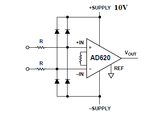
but in AD620 datasheet the max input differential voltage must be 25 V so that i want to use diode to protect or to limit my input voltage as the supply voltage like what we see in attach
so can you give me some diode reference ???
protection input.png
 

Please give us more information on why your differential voltage is 27 V, ; what is the gain of your amplifier?
 

so can you give me some diode reference ???
Any (passably fast) silicon diode is fine, like e.g. 1N914, 1N4148 . With this type of input protection, you limit the differential input voltage to SUPPLY+2Vd, i.e. to <≈12V .
 
my application is that i want to measure the VOLTAGE of a contact RESISTANCE like what we see in the attach
CONTACT.png
 

in the ad620 datasheet the max differential input is 25 V so i want t o make protection for my input amplifier what do you think about this circuit is that the right one ?

AMPLIFIER.png
 

in the ad620 datasheet the max differential input is 25 V so i want t o make protection for my input amplifier what do you think about this circuit is that the right one ?

As I already told you above, your protection circuit is ok.

The AD620' (max.) input offset voltage of 125µV presumably is negligible.
 

Besides protecting the AD620 against damage, you would want to keep the measured voltage within the amplifier's common mode range. According to your schematic, this will never be the case, because the common mode voltage is either +13.5 or -13.5 V.
 
FvM is right. So you need a supply voltage of ±(16..18)V. Min. for w.c. over temperature is |13.5+2.1| = ±15.6V .
 
1) in my application the amplifier output voltage must be < 10 V so that my supply should be <= 10V
2) haw can i choose the resistance R1 and R2 ??
 

1) in my application the amplifier output voltage must be < 10 V so that my supply should be <= 10V
Because of your + or - 13.5V input voltage you need a power supply of > |13.5+2.1|V, i.e. min. ±16V to stay in the admissible input voltage range of the AD620 opAmp.

2) haw can i choose the resistance R1 and R2 ??
This isn't critical. Values from 10kΩ .. 1MΩ should be ok.
 

Status
Not open for further replies.

Similar threads

Part and Inventory Search

Welcome to EDABoard.com

Sponsor

Back
Top