Continue to Site

Welcome to EDAboard.com

Welcome to our site! EDAboard.com is an international Electronics Discussion Forum focused on EDA software, circuits, schematics, books, theory, papers, asic, pld, 8051, DSP, Network, RF, Analog Design, PCB, Service Manuals... and a whole lot more! To participate you need to register. Registration is free. Click here to register now.

[SOLVED] Actual circuit not behaving according to simulation

Status
Not open for further replies.

Jodh

Newbie level 6
Newbie level 6
Joined
Feb 11, 2015
Messages
12
Helped
2
Reputation
4
Reaction score
2
Trophy points
3
Location
India
Visit site
Activity points
89
I simulated the below attached circuit in Proteus 8 and it works fine. When I made the same circuit with actual components I got the following problems:

1. The port 0 has all pins at 5V DC, I grounded the switches to account for that, but I dont know if the 5V is floating state or high logic in the above case.
2. Both my relays get switched ON and stay that way. I think the current from my port 2 is not enough to drive the uln2003an, will adding a pull up resistor solve it?
3. In my actual circuit I am using ILN2003an, i checked the datasheet and both seem the same to me.
Any suggestion as to correct my circuit or code will be appriciated.If my circuit is correct, I can then start troubleshooting for actual hardware faults instead of logical errors.

Regards
Jodh
CODE : View attachment test.txt
Circuit : circuit.PNG
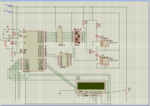
 

Since no one has answered my query. I will add a bit more detail about what the circuit is meant to do.The objective is to switch the relays (ON-OFF) for a specific number of cycles. the cycles are decided by the DIP switches connected to port 0.The number of cycles left are dislayed on the LCD. Right now niether by LCD is displaying anything nor are the relays switching they just remain ON. I really need to find the problem. Please help me.
 

Port0 is input port ,so you have to make it as input by PORT0=0Xff,
The 89c51 ports can only be made as active low, Is that your DIP swith connected as active low?
 

the common point of switch should be connected to ground. is uln2003 is proper grounded? you can add pull up to uln i/p pins
 
  • Like
Reactions: Jodh

    Jodh

    Points: 2
    Helpful Answer Positive Rating
1. Yes I have made P0 as input by putting 0xff.
2. I grounded the DIP switches.
3. I removed the uln and checked the output at P2.6 and P2.7 and it works as expected. Only when I apply the uln and the relays(load) the circuit misbehaves, I think it is due to insufficient current from the uC pins i.e. the uC is unable to drive the ULN and relays.
4. I checked the ULN ground.
5. Also I found that current leaks from the relay coil, as when I gave +5V to the first LED and ground at 1C of ULN where the LED is connected, both the LED glow.

SO my final question is how can I modify the relay circuit to account for this.

PS: thank you for your replys. Here is the zip file.
 

Attachments

  • test.txt.zip
    946 bytes · Views: 133

I feel so stupid right now!
My only mistake was that I was applying inverted power supply to the relay. -24V instead of 24V. F##k me, right?

Now the only problem left is troubleshooting the LCD circuit. Hahaha.
 

Put a 100 nF and 10uF electrolytic across VDD and VSS pins of 8051 and close to 8051. Across each relay coil put a 1N4007 in reverse and a 100 nF.

In lcd_ini() function before the first lcd_cmd() function call put a 120 ms delay.
 
Last edited:

you cant display the numbers on LCD after 9 so split them.like below and then converting them to ASCII.
Code:
unsigned short temp=0;//temp is the variable
lcd_cmd(0x81);
temp = (cycles / 100) ;		
	lcd_data(temp+ 48);
	temp = ((cycles % 100)/10);
	lcd_data(temp + 48);
	temp = ((cycles % 100)%10) ;
	lcd_data(temp + 48);

If you look at my code you will see that the number is split and then 48 is added induvidually to each digit, therefore I can display numbers greater than 9. Besides the simulation is working perfectly so the code must be correct.

- - - Updated - - -

Put a 100 nF and 10uF electrolytic across VDD and VSS pins of 8051 and close to 8051. Across each relay coil put a 1N4007 in reverse and a 100 nF.
I thought the ULN is supposed to provide a diode for the inductive effect. What are the capacitors at VDD and VSS used for?

In lcd_ini() function before the first lcd_cmd() function call put a 120 ms delay.
What is the reason for putting the delay?Is it something to do with sufficient time for lcd to initialize, before the while loop starts?
 

In the end it was only human error that prevented the circuit to work. After correcting the LCD VCC and VDD connections and correcting the contrast everything worked according to plan, except one minor change from the simulated circuit, the switches had to be grounded instead of pulled up.
With this I am marking this thread as solved and I want to thank, in no particular order, Mukesh, welove9051, milan and aamer for their valuable inputs.
 

Status
Not open for further replies.

Part and Inventory Search

Welcome to EDABoard.com

Sponsor

Back
Top