mike buba
Member level 2
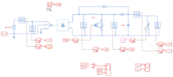
Hi, initially I am trying to reduce noise in my Active PFC circuit (see this thread), and while doing more testing and simulations I discovered interesting voltage waveforms across the switch. My model looks like this:
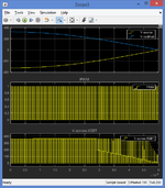
And when I record voltage I get this. Only 1/4 of the period is shown and the second figure shows detail.
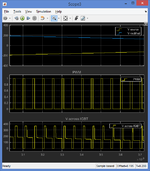
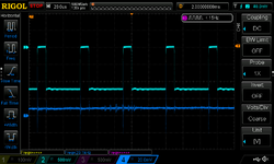
I would expect the voltage to be equal to the PWM pulses... in that way, I could focus on identifying reverse recovery spikes and reducing noise (this thread still active). I am also measuring something similar in the real system:
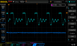
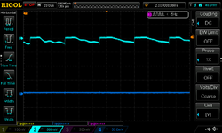
If I put another capacitor, e.g. 2.4 mF, at the rectifier output, the MATLAB Simulink simulation does not give this 'strange' voltage waveform across IGBT, i.e. it is significantly reduced.
But Active PFC schematics on the web do not show any capacitors at the rectifier outputs (e.g. 1, 2 or 3).
Should I go with full-wave rectified voltage or try to smooth it by adding capacitors?

And when I record voltage I get this. Only 1/4 of the period is shown and the second figure shows detail.


I would expect the voltage to be equal to the PWM pulses... in that way, I could focus on identifying reverse recovery spikes and reducing noise (this thread still active). I am also measuring something similar in the real system:


If I put another capacitor, e.g. 2.4 mF, at the rectifier output, the MATLAB Simulink simulation does not give this 'strange' voltage waveform across IGBT, i.e. it is significantly reduced.
But Active PFC schematics on the web do not show any capacitors at the rectifier outputs (e.g. 1, 2 or 3).
Should I go with full-wave rectified voltage or try to smooth it by adding capacitors?