Continue to Site

Welcome to EDAboard.com

Welcome to our site! EDAboard.com is an international Electronics Discussion Forum focused on EDA software, circuits, schematics, books, theory, papers, asic, pld, 8051, DSP, Network, RF, Analog Design, PCB, Service Manuals... and a whole lot more! To participate you need to register. Registration is free. Click here to register now.

active low pass filter circuit design problem

Status
Not open for further replies.

466576266

Member level 1
Joined
Mar 22, 2010
Messages
36
Helped
0
Reputation
0
Reaction score
0
Trophy points
1,286
Location
ShangHai,China
Activity points
1,541
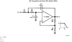
hey, recently i am designing an active filter circuit. but i meet with a problem. as u can see the pic, the fliter chip is from the national semiconductor. well, the focus is the calculation.

i know how to calculate two fo them: Fo=1/2*3.14*R1*C1
Av=1+R3/R4

But how to calculate the Q, and what is real meaning ? anybody can solve this problem, and some materials related with the Q is ok.

thanks in advance.
 

Attachments

  • lm358.png
    lm358.png
    34.3 KB · Views: 120

Q for a low-pass filter?
Yes... it gives an indication on how fast the response of a step signal is.


For band-pass filter.

Edited
Q= BW/fo wrong!
Q= fo/BW
So high Q means the pass-band filter is more selective around fo.

where
BW is the 3db bandwidth of the band-pass filter.
fo is its mid frequency (or resonant frequency)

Added:
The circuit of interest here is of Sallen-Key Architecture.

Added:
For this circuit:
Q = 1/(3-Av)

Added:
One of the good references for low pass filters is from TI.
www.science.unitn.it/~bassi/Signal/TInotes/sloa049.pdf
 
Last edited:
Forget the given formula for Fo. That's applicable for a 1st order lowpass only.
Here you have a second order active filter, which has to be calculated according to the rules that apply to an opamp with feedback. I assume you are familiar with opamp circuits.
When you compare the result (2nd order transfer function, assuming an ideal VCVS with a gain of 2) with the standard 2nd order filter formula you can derive the expression for the pole data (pole Qp and pole frequency wp). This standard low pass expression contains Qp as well as wp as coefficients.
Remark: Because you are going to design a filter I presume that you are familiar with some filter basics. That`s the reason I do not simply provide you with the formulas. But they can be found in each relevant textbook.
 
Last edited:

first what i want to say is ads exists each corner in the world. just go to hell the ads.

thanks for ur quick response. i am just a beginner to the filter design , and the circuit accuracy is not of the most interest. of course, if u can give me the formula, i will be much appreciate.

by the way, thank u all the same.
 

I am afraid, it is applicable here too... since R1=R2 and C1=C2... right?

May be - as the outcome of the calculation. I don't think that it helps the questioner if we simply give the formula for Fo.
As he is a beginner I am afraid he does not know about the meaning of the pole frequency, because (for Qp=1) it differs from the band edge frequency. I have tried to motivate him to calculate by himself.

---------- Post added at 12:39 ---------- Previous post was at 12:30 ----------

Q for a low-pass filter?
Yes... its inverse gives an indication on how fast the response of a step signal is.

Kerim, did you never hear about the "pole quality factor " Qp ?
It is defined not in the time domain but in the frequency domain and describes - together with the pole frequency - the pole location in the s-plane. However, its effect can be seen also in the time domain (as mentioned by you).
 

I got your point only after I replied you... :)

========

You are right, I remember now... "pole quality factor".
At work, in the last decade, I always used to visualize/calculate the analogue responses in the time domain only. So I think, I am missing now many theorems, definitions... etc, of the other domains which were introduced to ease solving the time domain equations in the first place.
 
Last edited:

thank u , Lvm. i am now collecting some materials related with filter degisn.

yeah, u r right. i should google some resources by myself, and not just turn to others for the end answer.
 

Good approach. So you are doing yourself a favour. If there is any specific question remaining - ask here in the forum.
 

haha, u r so nice. really thank u . if i come into any problem, i think i will turn to u for help.
 

hello, Mr LvW(maybe). i read some materials related with the low-pass filter design. and i find that the circuit i submited here yesterday is a classic sallen-key non-inverting filter topology circuit.

and the formula i mentioned here yesterday is absolutely wrong. and maybe the right formula is:

Fo=1/2*3.14*(√R1*R2*C1*C2)
Q=(√R1*R2*C1*C2)/(C2*R1+C2*R2)

of course, the Av calculation is right. any suggestions, Mr LvM...
 

This circuit, with a gain of 2, is actually a very nice one to analyze. The capacitors can be made equal in value. The resistors can then set the Q by being staggered geometrically. (R1*R2 = R^2, or Q*R*R/Q = R^2)
R1 = Q*R
R2 = R/Q
C1 = C2 = C
Av0 = 2
F = 1/(2*pi*R*C)

Though the gain=1 case is more common, as it has an easy implementation to get a Q of 0.707 -- a fairly common goal. (maximally flat frequency magnitude response for the 2 pole case)
 

Fo=1/2*3.14*(√R1*R2*C1*C2)
Q=(√R1*R2*C1*C2)/(C2*R1+C2*R2)

You did well. I mean you present now your own work so discussing the subject becomes more interesting.

For your specific circuit, we can deduce from your formula above:
Fo=1/(2*3.14*R1*C1)
Note: I think you meant writing the formula as:
Fo=1/(2*3.14*√(R1*R2*C1*C2))

For calculating Q (this Q is what makes the filter not being of 1st order though its Fo formula says it is) Av of this particular filter is:
Av = 1 + R4/R3 = 2 (because R3=R4)
And the general form of its Q is:

Q=√(R1*R2*C1*C2)/(C2*R1+C2*R2-C1*R1(1-Av)) wrong!
Edited:
Q=√(R1*R2*C1*C2)/(C2*R1+C2*R2+C1*R1(1-Av))

So your formula of Q here assumes that Av=1 that is R4 = ∞ (R4 removed).
But actually it is, after replacing Av=2:
Q=√(R1*R2*C1*C2)/(C2*R1+C2*R2-C1*R1)
Q= 1 (wow... too simple :wink: )

Please feel free to point out anything you find not logical so far.

On the other hand, you asked what could be the meaning of Q. Although I can see its effects on a filter but I think LvW may help you more in this respect.

Kerim
 
Last edited:

hey, Mr KerimF. i made a small mistake just. as u can see the formula i wrote above: Q=(√R1*R2*C1*C2)/(C2*R1+C2*R2). and this formula is wrong. i donnt take the Av into account.

and the formula u present:Q=√(R1*R2*C1*C2)/(C2*R1+C2*R2-C1*R1(1-Av))
maybe is not right

let us proceed the calculation:

1:my formula is based on the unity-gain calculation.
with my formulation:Q=(√R1*R2*C1*C2)/(C2*R1+C2*R2) the answer:Q=0.5


2:with ur formulation:Q=√(R1*R2*C1*C2)/(C2*R1+C2*R2-C1*R1(1-Av))
the answer is 1/3. and it's not 1!!!

am i right? looking forward to ur response...
 

Thank you... I mistyped the sign of C1*R1(1-Av), the right formula is:
Q=√(R1*R2*C1*C2)/(C2*R1+C2*R2+C1*R1(1-Av))
So
Q=1 (if Av=2)
 

yeah, that's right now.

wow, the problem is finally solved. and the right formula to be used for the circuit are:

1:Av = 1 + R4/R3

2:Fo=1/(2*3.14*√(R1*R2*C1*C2))

3:Q=√(R1*R2*C1*C2)/(C2*R1+C2*R2+C1*R1(1-Av))

if someone has any doubt about them. just "speak" it out.

by the way, thanks everyone....
 

Quote Kerim: On the other hand, you asked what could be the meaning of Q. Although I can see its effects on a filter but I think LvW may help you more in this respect.
Kerim


OK, here are some basics regarding Qp:
*General: Qp is a quality factor for a conjugate-complex pole pair in the s-domain.
* Qp=1/(2*d) with d= damping factor from classic physics.
* More related to filters: Qp=1/(2*cos(phi)) with phi=angle between neg. real axis of the s-plane and the vector pointing to the pole location in the left half of the s-plane.
*For phi=90 deg Qp approaches infinite (oscillation condition with a pole on the imag. axis).
*Frequency domain: Qp is a rough measure for transfer function peaking in the vicinity of the pole frequency wp.
The pole frequency wp is the magnitude of the vector mentioned above.
*Examples: For Qp=0.7071 (and smaller) there is no peaking at all (Butterworth response: Qp=0.7071)
*Time domain: Qp is a rough measure for the overshoot (ringing amplitude) of the step response.
Examples: Qp infinite: continuous ringing (oscillation); Qp=0.7071: overshoot 4.3%; Qp=0.5 with no overshoot at all.
*Pole data Qp and wp are given for all relevant lowpass approximations (Bessel, Butterworth, Chebyshev,...) in textbooks resp. filter design tables (programs).
__________________________

All for now.
LvW

---------- Post added at 11:19 ---------- Previous post was at 10:25 ----------

To complete the story one additional remark:
In case of a bandpass the Qp value as described above is identical to the "classical" quality figure Q=fo/BW (in contrast to the expression given by Kerims first reply). This justifies the definition.
 

You are totally right, LvW... and thank you for correcting the Q formula... I have to be more careful in the future because... you are not around here always :smile:
 

Status
Not open for further replies.

Similar threads

Part and Inventory Search

Welcome to EDABoard.com

Sponsor

Back
Top