allennlowaton
Full Member level 5
Hello EDA fellows,
I would like to ask some help regarding the
active input regulated cascode current mirror.
Shown below is my circuit.
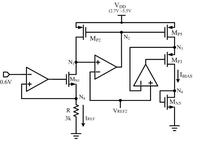
I need to obtain an IBIAS to be a multiple of IREF but
I'm having a difficulty in achieving this.
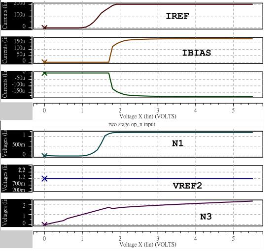
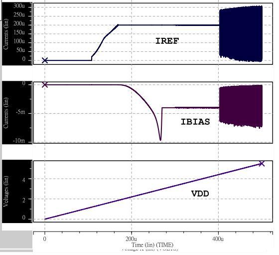
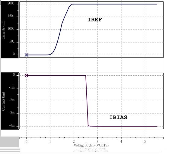
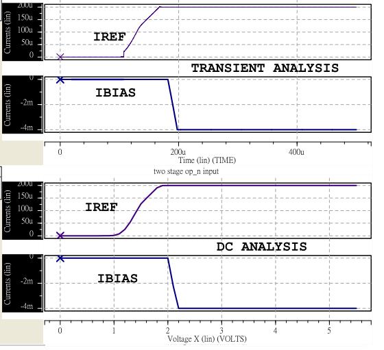
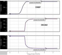
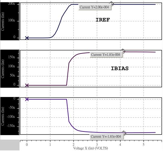
Shown below is my resulted HSPICE simulation.
I have observed that I can't make the nodes N1 and N3 to be the same.
I don't understand why.
Thank you for taking time on this.
I would like to ask some help regarding the
active input regulated cascode current mirror.
Shown below is my circuit.

I need to obtain an IBIAS to be a multiple of IREF but
I'm having a difficulty in achieving this.
Shown below is my resulted HSPICE simulation.
I have observed that I can't make the nodes N1 and N3 to be the same.
I don't understand why.
Thank you for taking time on this.