Continue to Site

Welcome to EDAboard.com

Welcome to our site! EDAboard.com is an international Electronics Discussion Forum focused on EDA software, circuits, schematics, books, theory, papers, asic, pld, 8051, DSP, Network, RF, Analog Design, PCB, Service Manuals... and a whole lot more! To participate you need to register. Registration is free. Click here to register now.

Active inductor simulation

Status
Not open for further replies.

bicave

Full Member level 1
Joined
Jun 19, 2006
Messages
97
Helped
4
Reputation
8
Reaction score
2
Trophy points
1,288
Activity points
1,910
Hi All,

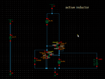
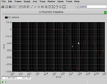
I'm simulating active inductor and see the value imaginary of Z in SP simulation. The sim results look strange and I don't understand where is the mistake in circuit or sim.
Pls see the attached.

It seems more than one resonant value, even it negative value.
could you give me advice ? or working active inductor. This is my first design follow some paper, I expect it works to understand more about aative inductor behavior.

thanks,
 

Attachments

  • circuit.png
    circuit.png
    31.6 KB · Views: 111
  • acsim.png
    acsim.png
    30.9 KB · Views: 100

Hi bicave

I'm simulating active inductor, but I am newbie too , why you put capacitor between drain and source? are the transistors in saturation region?
 

inductance value is gm1.gm2/C, I add this cap for testing L.
 

but I think inductance value is : Leq=Cgs2/(gm1*gm2)
and active inductor converts parasitic capacitance of transistor to inductance and no need to add external C here
 
Anyone know how to simulate gm, or just rely on hand calculation?
 

Anyone know how to simulate gm, or just rely on hand calculation?

just use annotation of DC operating point or print function in analog design environment
 

Status
Not open for further replies.

Part and Inventory Search

Welcome to EDABoard.com

Sponsor

Back
Top