Continue to Site

Welcome to EDAboard.com

Welcome to our site! EDAboard.com is an international Electronics Discussion Forum focused on EDA software, circuits, schematics, books, theory, papers, asic, pld, 8051, DSP, Network, RF, Analog Design, PCB, Service Manuals... and a whole lot more! To participate you need to register. Registration is free. Click here to register now.

active high-pass filter design - chebyshev 7th order

Status
Not open for further replies.

abbey

Junior Member level 1
Joined
Feb 9, 2010
Messages
16
Helped
0
Reputation
0
Reaction score
0
Trophy points
1,281
Location
abbey
Activity points
1,395
active high-pass filter

I was given a task of designing an active high-pass Chebyshev 7th order filter.I can choose any frequency etc.Can anybody help me or is there any link so I could find the transfer function and the parameters of the circuit?
 

active high-pass filter

The easiest way is with some design software, particularly if you want to check the sensitivity of the design to component tolerances. I don't know of any free software that will do 7th order, although there may be some. I use Nuhertz Filter Solutions which is pretty good (but expensive). I may have useful data in my filter design books if you give me the passband ripple you want.

Keith.
 

Re: active high-pass filter

keith1200rs said:
The easiest way is with some design software, particularly if you want to check the sensitivity of the design to component tolerances. I don't know of any free software that will do 7th order, although there may be some. I use Nuhertz Filter Solutions which is pretty good (but expensive). I may have useful data in my filter design books if you give me the passband ripple you want.
Keith.

The problem with filter design software is that in most cases only cascade topologies are supported (chain of second order stages). But, for higher order filters (above, let`s say 6th order) this cascade approach is not to be recommended due to parameter tolerances and tuning problems. The best solution is an active realization of a passive ladder structure (leap frog technique or inductor simulation). But - as mentioned - in many cases this is not supported by programs.
However, one exception just comes into my mind: Filter solutions (Nuhertz tech.) is able to design active ladder structures.
 

Re: active high-pass filter

LvW said:
However, one exception just comes into my mind: Filter solutions (Nuhertz tech.) is able to design active ladder structures.

Yes, that is why I bought the software! I assume this is the sort of design you are looking for?

Keith.
 

Re: active high-pass filter

keith1200rs said:
Yes, that is why I bought the software! I assume this is the sort of design you are looking for?
Keith.

Yes, I agree. That's the best design.
 

active high-pass filter

Tell me the ripple & cut off & I will run it for you - it only takes a minute. Do you have a Spice simulator? The best way I found of checking the design is to draw it in Spice. While Nuhertz allows you to set the "real" opamp characteristics it's model of opamps is quite crude. You are better off running it through Spice with a decent opamp model and doing a Monte Carlo or worst case analysis.

I used the ladder design for a complex filter and it worked very well.

Keith.
 

Thank you very much!They were really flexible about the ripple and cut-off frequency.So I can choose any of these.I do have a spice simulator so I could run any schedule.However,i chose to use a sallen-key topology.I hope that it's not a bad choice.
 

Something like this? 1dB ripple, 1kHz cut off. You can just scale the values to shift the cut off frequency.

Keith.

edit: you may also want to adjust the values to get sensible value capacitors
 

abbey said:
Thank you very much!They were really flexible about the ripple and cut-off frequency.So I can choose any of these.I do have a spice simulator so I could run any schedule.However,i chose to use a sallen-key topology.I hope that it's not a bad choice.

I will not say "bad choice". But surely not the best choice! The S&K topology is rather sensitive to component tolerances (if compared with the active ladder approach).
Of course, this cannot be observed during simulation. For ideal conditions, all filter topologies are equal! You can see the differences only under non-ideal conditions.
Anyway, good luck.
 

The ladder would be my choice, but the sensitivity to component tolerances will show up in a worst case or Monte Carlo simulation so you can decide then.

Keith
 

Has anyone try 7th order chebyshev LPF cutoff at 68MHz? The R value is too small for active filter. I am going to try lumped element filter design instead. But how do you simulate the parasitic in ORCAD PSPICE?
 

What topology are you looking at? 7th order with 1k resistors with GIC Biquad/Ladder comes around 3pF to 2.5pF. The problem is you need 1GHz opamps, I think. Not necessarily impossible, but certainly tricky.

For simulating LC filters you need to create real models of all your devices. Capacitor parasitics you can get from manufacturers. Kemet & AVX have some software which will give you Spice models I think. Inductors tends to be DIY, although I think some companies such as Coilcraft have some Spice models. Otherwise it's down to creating your own from whatever information you have such as Q and SRF.

I am not sure how the tolerancing would work out with an LC filter. Maybe you should try that out first before you bother with proper models.

Keith.
 

@keith1200rs

Thanks for your comments. I was looking into Sallen & key topology. Analog Devices has an 1GHz op-amp, AD8045 that meets my requirements. The tricky part for this implementation is the low resistor value ~3.5 Ohm , with preset resistor at 1K Ohm and 56pF cap. I am not familiar with GIC Biquad topology , do you care to share if this would be better design for higher order filter?
 

You said chebyshev, but didn't mention the type and ripple. Generally, a passive implementation with good chip inductors is
the best way for the intended frequency range, I think.
 

@ FvM

I agree. But I concern about the ability to simulate the parasitic impedance with PSPICE, plus I also need to incorporate a gain stage right after that. I was thinking using active filter that may simplify the design.

By the way, that is for a 0.3dB p-p ripple LPF.
 

marcovaldo2000 said:
@ FvM

I agree. But I concern about the ability to simulate the parasitic impedance with PSPICE, plus I also need to incorporate a gain stage right after that. I was thinking using active filter that may simplify the design.

By the way, that is for a 0.3dB p-p ripple LPF.

Pspice has the ability to simulate it, the tricky part is creating all the models for all the parts!

Sallen Key is not the way to go. The bandwidth requirements are crazy.

Here is a GIC Ladder implementation.

I have to say though, I agree with other comments that you should look at passive. I have used quite a few 1GHz to 2GHz opamps but I have never tried making filters with them and I'm not sure they would be ideal. Still, you could easily simulate it first.

I have done 5 & 6 pole Cheby LP with LC and they have worked fine. I seem to remember the tricky bit is the inductor series resistance can be a problem so you may need to tweak some values to get back to the right response. And you have to watch out for tolerances of course, but that is true for any high order filter.

Keith.
 

keith1200rs said:
marcovaldo2000 said:
@ FvM

I agree. But I concern about the ability to simulate the parasitic impedance with PSPICE, plus I also need to incorporate a gain stage right after that. I was thinking using active filter that may simplify the design.

By the way, that is for a 0.3dB p-p ripple LPF.

Pspice has the ability to simulate it, the tricky part is creating all the models for all the parts!

Sallen Key is not the way to go. The bandwidth requirements are crazy.

Here is a GIC Ladder implementation.

I have to say though, I agree with other comments that you should look at passive. I have used quite a few 1GHz to 2GHz opamps but I have never tried making filters with them and I'm not sure they would be ideal. Still, you could easily simulate it first.

I have done 5 & 6 pole Cheby LP with LC and they have worked fine. I seem to remember the tricky bit is the inductor series resistance can be a problem so you may need to tweak some values to get back to the right response. And you have to watch out for tolerances of course, but that is true for any high order filter.

Keith.

@Keith

Thanks for your insight and I really appreciate your help. I definitely looking into passive elements while trying this design that you proposed. Do you have any suggestion for books or articles that has more detailed filter design ( including GIC Ladder topology you proposed. )
I am very grateful you guys are being really helpful.Thanks.
 

I have a Filter Design Handbook but I must admit I have never been that keen on it. It is heavy going and too theoretical for me. I like books that get stuck in to practical designs quickly.

The help file in Nuhertz filter software gives a good overview. You can only do 3 pole with the free version. https://www.nuhertz.com/

For passive filters I have tended to use Chris Bowick's RF Circuit Design. Maybe a bit old and dated, but practical and straight to the point.

Keith.
 

When building active filters in the 100 MHz or above region with GHz OPs, you'll mostly notice a Q increase. If you try to handle
it by a recalculation of filter parameters, you realize, that you got additional poles that prevent an exact implementation of the intended
filter characteristic. You also realize, that the simulation models provided by the OP manufacturers reproduce the small signal behaviour
moderately (at best) and the large signal behaviour of the chip poorly. Simulation of LC filters gives excellent results compared
to the former.

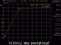
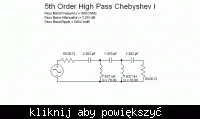
As a practical example, I have a 5th order HP design with nominal 800 MHz cut-off, that was assembled from 5% 0603 chips (wirewound
inductors and standard NP0 capacitors). I also show the real |S21| measurement. You can see some deviations, but it's rather near to the
nominal characteristic. No other parasitics than the limited inductor Q have been considered. Seriously, you can't expect a similar
result from a x00 MHz active Filter.


Status
Not open for further replies.

Similar threads

Part and Inventory Search

Welcome to EDABoard.com

Sponsor

Back
Top