Welcome to our site! EDAboard.com is an international Electronics Discussion Forum focused on EDA software, circuits, schematics, books, theory, papers, asic, pld, 8051, DSP, Network, RF, Analog Design, PCB, Service Manuals... and a whole lot more! To participate you need to register. Registration is free. Click here to register now.
Choose a passive RLC structure (L must be grounded) and simply replace L by the active inductor.
---------- Post added at 10:56 ---------- Previous post was at 10:50 ----------
Most simple solution: Series combination of a resistor and a grounded LC parallel resonance circuit.
You can use the low-impedance opamp output as bandpass output.
Normally, an active inductor comprises two opamps in form of a GIC combination.
As far as I understood you, your active circuit (one opamp?) simulates an R-L combination. Right?
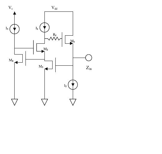
To avoid misunderstandings, show your circuit.
Sorry, I could not know.
Do you know the passive equivalent that is "simulated" with your active circuit?
As mentioned before, choose a passive RLC structure and replace the corresponding part by the active unit(s).
As a first attempt you should place a suitable shunt capacitor in parallel to the R-L combination and a use an additional series resistor Rs to connect the signal source.
If the loss resistance of the inductor is relatively small you should get a bandpass response at the node between Rs and the tank circuit.
This site uses cookies to help personalise content, tailor your experience and to keep you logged in if you register.
By continuing to use this site, you are consenting to our use of cookies.